Qualcraft HitchClip User Manual
Page 2
Installation and Use
Prior to installation:
Ensure minimum substrate thickness requirement is met, ensure all obstructions/debris are removed from substrate, and eliminate/minimize all swing fall
hazards. HitchClip™ may be used in multiple installation applications. ALWAYS use new fasteners for each new installation application. All connections must
be selected and deemed compatible with HitchClips™ by a Competent Person. Read and understand all instructions provided with accessories to be used in
combination with HitchClip™.
Minimum substrate thickness requirements:
• Wood: 1/2” CDX plywood sheathing and 3“ support beam.
• Metal: HitchClip™ may be installed onto metal substrates, providing there is a sufficient framing member beneath, as determined by a Competent Person.
• Compatible pitch range: flat - vertical/sheer.
Recommended fasteners (Not included. Use either screws OR nails):
• (6) 2½” #10 Grip-Rite exterior screws, or equivalent, as determined by Competent Person.
• (6) 16d galvanized framing nails.
Installation:
1. Installation location must be selected and deemed compatible with HitchClip™ by a Competent Person.
2. Place HitchClip™ at selected installation location and install all fasteners. HitchClip™ must lie flush
against substrate. Fasteners must be installed through roof sheathing and into truss or compatible
support beam. Minimum fastener embedment in support beam is 2”.
3. All (6) nails OR all (6) screws must be used, and must by fully embedded through sheathing and
into truss or compatible support beam.
4. Connect complete and compatible PFAS to HitchClip™ connection point OR install compatible HitchClip™
accessory according to instructions provided with accessory. When used with compatible accessory,
NEVER make any other connections to HitchClip™.
Components and Specifications
Materials: aluminum.
Minimum breaking strength: 5,000 lbs.
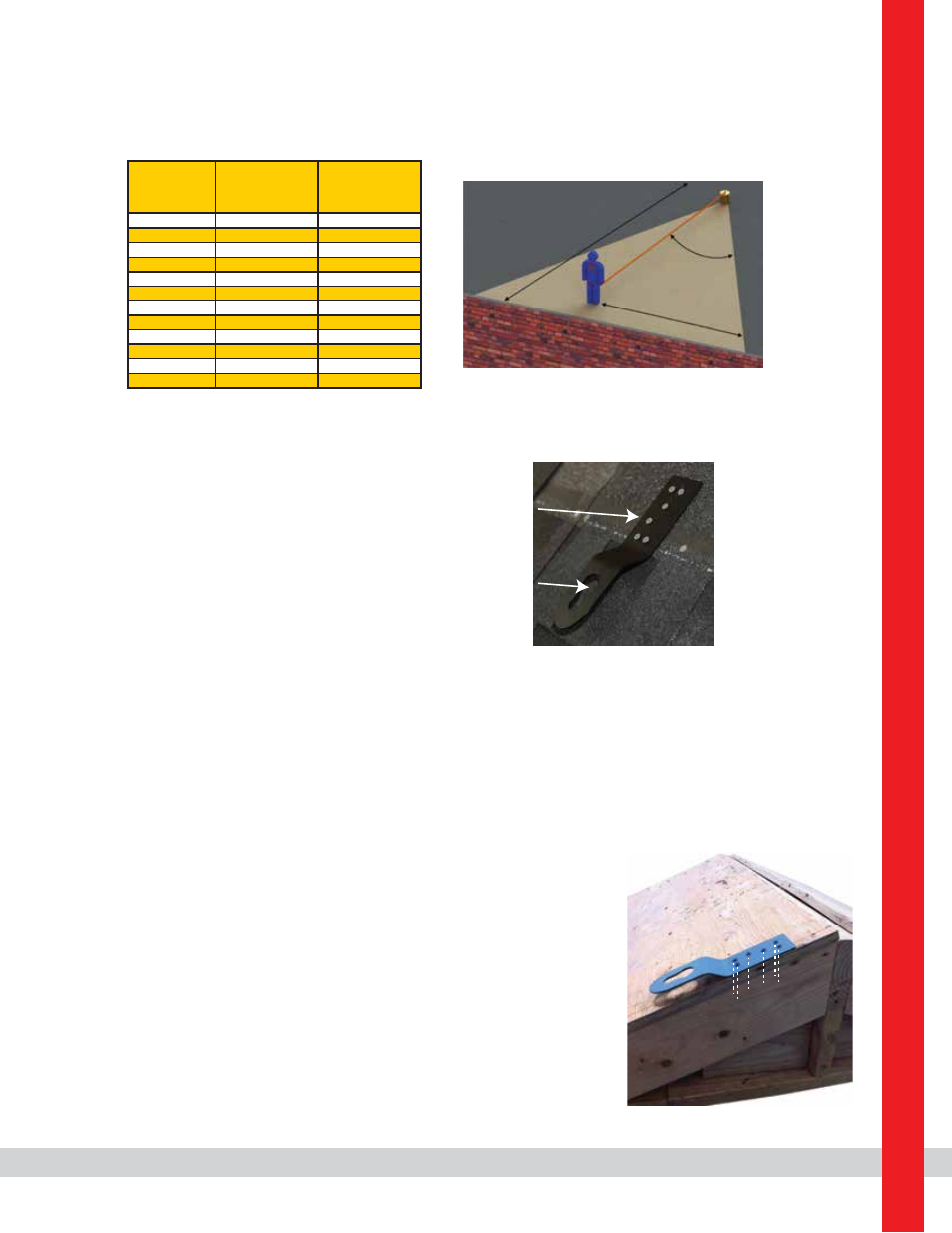
The below charts detail allowable working zones required to reduce risk of swing falls and improper side loading.
ALWAYS adhere to information specified by charts.
Anchor Distance
From
Leading Edge (Y)
Working Distance
Along Roof Edge
(Either Direction) (X)
Working Angle
From
Perpendicular (Ø)
6’
10’
15’
20’
25’
30’
35’
40’
45’
50’
55’
60’
8’
9’ - 9”
11’ - 7”
13’ - 3”
14’ - 6”
16’
17’ - 2”
18’ - 3”
19’ - 4”
19’ - 10”
21’ - 4”
22’ - 3”
53°
45°
38°
33°
30°
28°
26°
24°
23°
21°
21°
21°
For example, if the anchorage connector is 6’ from the leading edge (Y), the working distance (X)
is 8’ in each direction from the perpendicular, which translates to a 53° working angle.
Key:
X: Working Distance
Along Roof Edge
Y: Distance From
Leading Edge
Ø: Total Working
Angle
Y
X
Ø
Connection point
Fastener installation
location (6)
Q
ua
lc
ra
ft
In
du
st
rie
s
6
0
M
ap
le
S
t.
, P
.O
. B
ox
3
6,
M
an
sf
ie
ld
, M
A
0
20
48
ph
on
e:
(
80
0)
2
31
-5
64
7
w
w
w
.q
ua
lc
ra
ft
.c
om
85144 (Rev. E)