Powermate PM0558023.01 User Manual
Page 7
STARTING THE ENGINE
1.
Check oil level and fuel.
2.
Disconnect all electrical loads from the unit.
3.
Adjust choke as necessary.
4.
Set the engine switch to the “ON" position.
5.
On electric start models, turn the key switch to “START”.
Release key switch after the engine starts. As the engine
warms up, readjust the choke.
WARNING: Provide adequate ventilation
for toxic exhaust gases and cooling air flow.
BREAK-IN PROCEDURE
Controlled break-in helps insure proper engine and
generator operation. Follow engine procedure outlined in
engine manual.
CAUTION: Do not apply heavy electrical load
during break-in period (the first two to three
hours of operations).
CAUTION: Allow generator to run at no load
for five minutes upon each initial start-up to
permit engine and generator to stabilize.
SHUTTING THE GENERATOR OFF
1.
Remove entire electrical load.
2.
Let the engine run for a few minutes without load.
3.
Move the engine switch to the “OFF” position. (Turn
the key switch to “OFF” on the electric start models).
4.
Do not leave the generator until it has completely stopped.
5.
Let unit completely cool prior to applying any protection
covers.
APPLYING LOAD
This unit has been pretested and adjusted to handle its full
capacity. When starting the generator, disconnect all load.
Apply load only after generator is running. Frequency and
voltage are automatically regulated for correct output. Do not
attempt to adjust engine speed.
CAUTION: When applying a load, do not
exceed the maximum wattage rating of the
generator when using one or more
receptacles. Also, do not exceed the
amperage rating of any one receptacle.
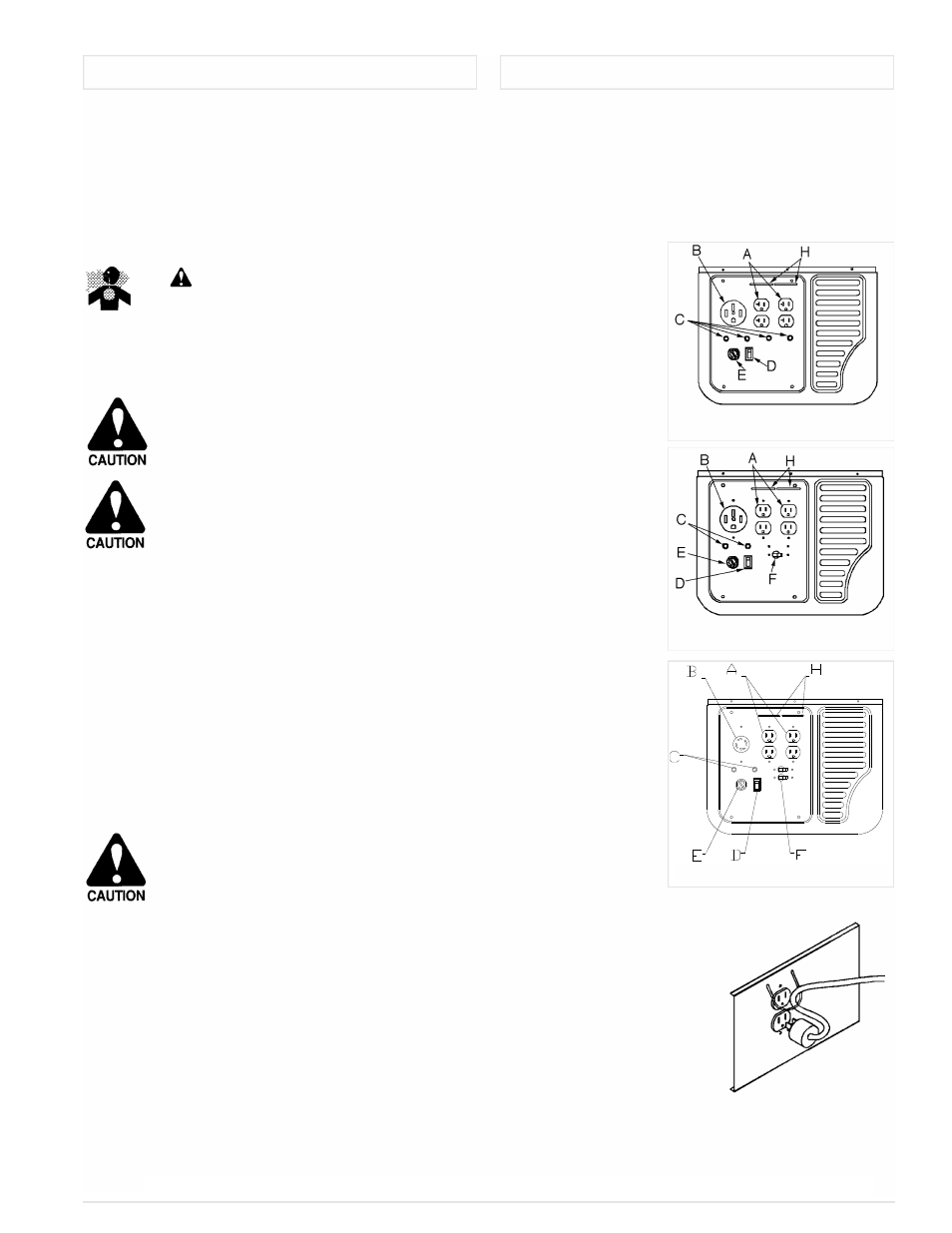
A. 120 V/20 Ampere Duplex Receptacle
NOTE: PC models use 120V/15 Ampere Duplex
Receptacles
There are five receptacles on the control panel. These
receptacles may be used in any combination provided that the
total wattage supplied by all receptacles at one time does not
exceed the name plate wattage rating of the generator.
There are two - 120 volt 20 amp duplex receptacles (A)
and one 120/240 volt high
power receptacle (B). Do
not draw more than 20
amps from any one of the
four 120 volt receptacles
(A). Also, if more than one
of the four receptacles are
used at the same time, the
load should be split
between the left and right
duplexes.
The high power
receptacle (B) should be
used to connect 240 volt
loads or high amperage
120 volt loads. (refer to
power cord connections to
determine proper
connection to this
receptacle.)
B. 120/240 Volt Heavy
Duty Receptacle
This receptacle is
rated for the maximum
output of the PM series
units. PC series uints
have 30 amp rated
receptacles. If this
receptacle is used along
with the 120 volt
receptacles, the total load
drawn must not exceed
the nameplate ratings.
C. and F. Circuit
Breakers
All receptacles are
protected by an AC circuit
breaker. (See Circuit Protection).
D. Idle Control Switch
Some models are equipped
with an idle control switch. (See
Idle Control).
E. Key Start
Used on electric start models.
H. CordKeeper™
The CordKeeper™ is a
unique feature used to prevent
plugs from being pulled out of the
120-volt receptacles.
GENERATOR OPERATION
MAJOR FEATURES on CONTROL PANEL
PM0557523.9 & PM0555523
PM0558023
7
English
Proper Use Of
CordKeeper™
PC0557523.8 & PC0555523.01