Assembly instructions, This completes assembly – MoJack PRO User Manual
Page 5
MoJack PRO Lift
MoJack PRO Lift
8
9
Assembly Instructions
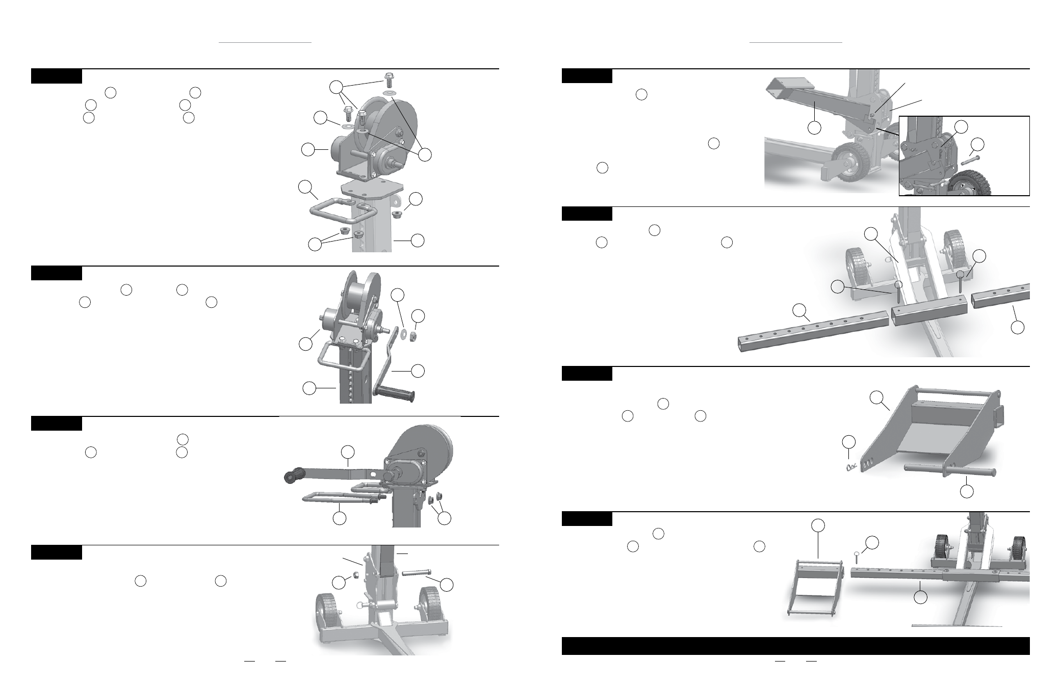
STEP 6
Attach the Ratchet Release Handle to the top
of the Tower using Nylock Nuts and tighten
as shown.
8
1
17
Ratchet Release Handle 8
Nylock Nuts
17
Winch Handle 10
STEP 7
Attach Lifting Strap from Winch Spool to the
Carrier using Cap Screw and Nylock Nut
and tighten as shown.
Note: Do not over tighten Nylock Nut.
23
24
Hex Nut 24
Cap Screw
23
Lifting Strap
Carrier
Attach the Winch and Grip Handle
to the Tower using Cap Screws ,
Nylock Nuts and Winch Washers ,
and tighten as shown.
STEP 4
9
1
7
16
17
Nylock Nuts 17
Cap Screws 16
Grip Handle 7
Winch 9
Tower
1
Nylock Nut
17
STEP 5
Attach Winch Handle to Winch using
Nylock Nut and Winch Handle Washer
and tighten as shown.
10
9
14
Winch 9
Winch Handle Washer
19
Winch Handle
10
Tower 1
Nylock Nut
14
19
18
Winch Washer 18
Winch Washers
18
Assembly Instructions
THIS COMPLETES ASSEMBLY.
Wheel Pad 5
STEP 10
Ready the Wheel Pads for installation by adding
Support Rods and Hair Pins .
5
11
22
Hair Pin 22
Support Rod 11
Push Pin
21
STEP 11
Slide the Wheel Pads onto both sides of the
Lift Arm Inserts and secure with Push Pins .
Note: The Wheel Pads can be moved in or out to fit
different mower widths. Use the configuration that
works best with your model of lawn mower.
5
6
21
Lift Arm Insert 6
Wheel Pad
5
Lift Arm 2
Push Pin
21
Slide Lift Arm Inserts into both sides of the
Lift Arm and secure with Push Pins as shown.
STEP 9
6
2
21
Lift Arm Insert 6
Lift Arm Insert 6
Push Pin 21
STEP 8
Hang the Lift Arm on the Carrier by hooking
the slotted area of the Lift Arm under the top
bar of the Carrier. Lift Arm must be inserted
from the front and then lowered which fastens
Lift Arm into place. Insert Clevis Pin through
the hole in the Carrier and lock by fastening the
Hair Pin to the Clevis Pin.
2
20
22
Lift Arm 2
Top Bar of Carrier
Clevis Pin
20
Hair Pin
22
Carrier