Operation, Opera t or ʼs manual – Lincoln Electric IMT10135 WIRE FEEDER WELDER 180 User Manual
Page 11
OPERA
T
OR
ʼS
MANUAL
B-3
OPERATION
B-3
WIRE FEEDER WELDER (180 MODEL)
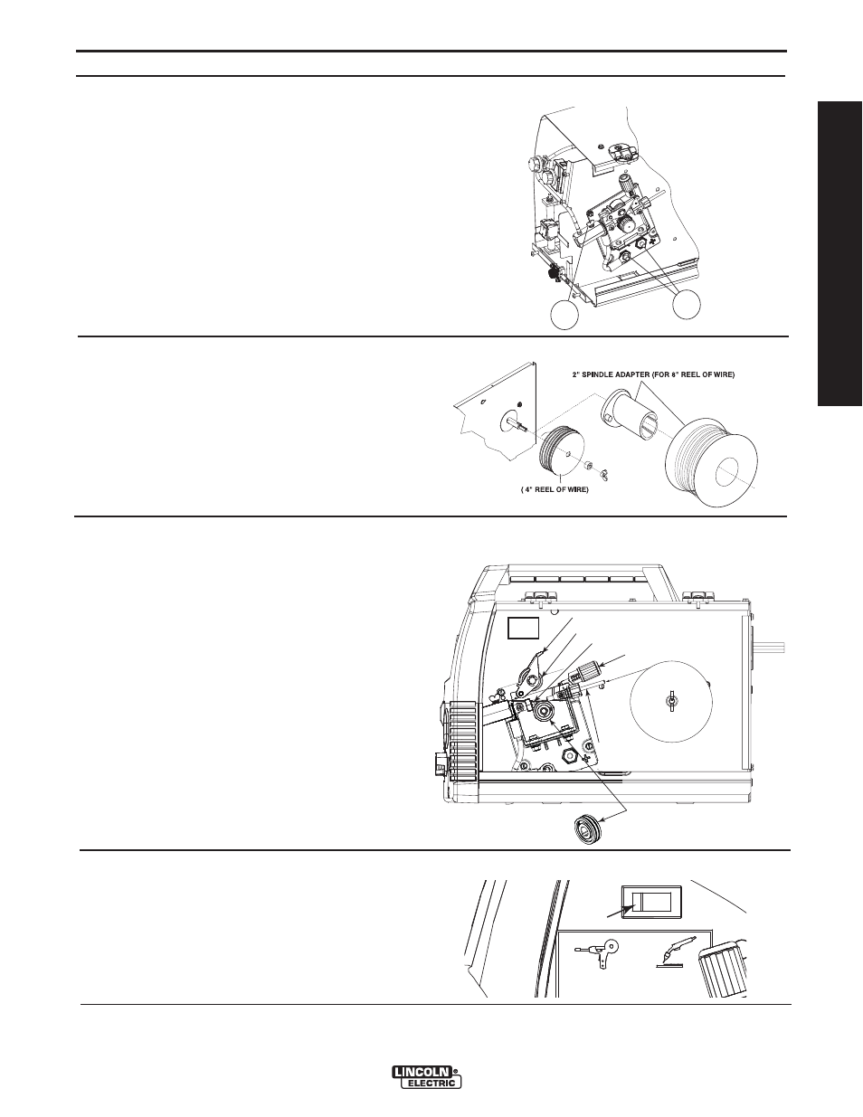
See Figure B.3
8. WELDING GUN CONNECTOR BUSHING &
THUMBSCREW – Provides electrical power to the
welding gun. The thumbscrew holds the welding
gun into the connector block. (Front Cover and Side
Door have been removed for clarity of Items 8 and
9).
9. OUTPUT TERMINALS - Connections to these ter-
minals determines the welding polarity, depending
on whether the process being used is flux-cored
welding or MIG welding.
See Figure B.4
10. WIRE SPOOL SPINDLE AND BRAKE – Holds a
4”(102mm) diameter spool. Use the 2”(51mm)
spindle adapter included with the machine for
8”(203mm) diameter spools. The wing nut sets
the brake friction to prevent the spool from over
rotating when the trigger is released. Tightening
the wing nut will prevent the spool from rotating
when the trigger is released.
See Figure B.5
11. WIRE DRIVE & COMPONENTS – Feeds wire
from the wire spool through the drive and through
the welding gun to the work piece.
a. Drive Roll – Drives the wire through the drive
system. The drive roll has grooves to match the
specific wire type and diameter. Refer to Table
B.1 for available drive rolls.
b. Incoming & Outgoing Guide – The wire is fed
through both guides. The Pivot Arm Assembly,
Tension Arm Assembly and Drive Roll keep
pressure on the wire in the groove.
c. Tension Arm Assembly – Turning clockwise
increases the forward force on the wire and turn-
ing counterclockwise decreases the force.
8
9
FIGURE B.3
FIGURE B.4
FIGURE B.5
FIGURE B.5a
WIRE SPOOL
.035" (0.9mm)
NR-211-MP
DRIVE ROLL
PIVOT ARM ASSEMBLY
TENSION ARM ASSEMBLY
OUTGOING GUIDE
INCOMING GUIDE
BEARING
See Figure B.5a
Magnum 100SG / Magnum 100L Switch - The
Magnum 100SG Spool Gun can be purchased at
authorized retailers. The part number is K2532-1.
MAGNUM 100SG
SWITCH
MAGNUM 100L