Installation, Identify and locate components, Included components – Lincoln Electric IMT10089 POWER MIG 180 DUAL User Manual
Page 8
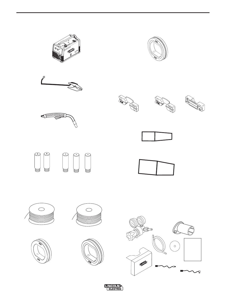
• .030 -.045(0.8-1.1mm) Knurled Drive Roll
(Installed on Machine).
• .025” -.035” (0.6 - 0.9mm) Inner Wire guide.
• .035” -.045” (0.9 - 1.1mm) Inner Wire Guide.
(Installed on Machine).
• Outer Wire Guide (Installed on Machine).
• Black Flux-cored Gasless Gun Nozzle (Installed on
Welding Gun).
• Brass MIG Gas Gun Nozzle.
• Regulator
• 2” Spindle Adapter
• Gas Hose
(For 8” Reel of wire)
• Learn to Weld (LTW1 Manual) • DVD
• 120V Input Cord
• Accessory Bag
• 230V Input Cord
DVD
GAS HOSE
ACCESSORY BAG
REGULATOR
2" SPINDLE ADAPTER (FOR 8" REEL OF WIRE)
120V INPUT CORD
230V INPUT CORD
LTW1
"LEARN TO WELD"
INCLUDED COMPONENTS
• Wire Feeder Welder.
• Work Cable & Clamp.
• Magnum 100L Welding Gun.
• 3 .035(0.9mm) Contact Tips (1 installed on the weld-
ing gun).
• 3 .025(0.6mm) Contact Tips.
• Spool of .035(0.9mm) diameter NR-211MP
Innershield Flux-cored Wire.
• Spool of .025(0.6mm) diameter L-56 MIG Wire.
• .025-.030(0.6-0.9mm) Smooth Drive Roll. • .035(0.9mm) Smooth Drive Roll.
.025
.025
.025
.035
.035
NR-211 MP
WIRE
L-56 MIG
INSTALLATION
POWER MIG® 180 DUAL
A-2
A-2
IDENTIFY AND LOCATE COMPONENTS
OUTER WIRE GUIDE
INNER WIRE GUIDE
.025-.035 (.6-.9mm)
INNER WIRE GUIDE
.035-.045 (.9-1.1mm)