Operation, Setting up and making a flux-cored weld, Drive roll and wire guides – Lincoln Electric IMT10089 POWER MIG 180 DUAL User Manual
Page 12
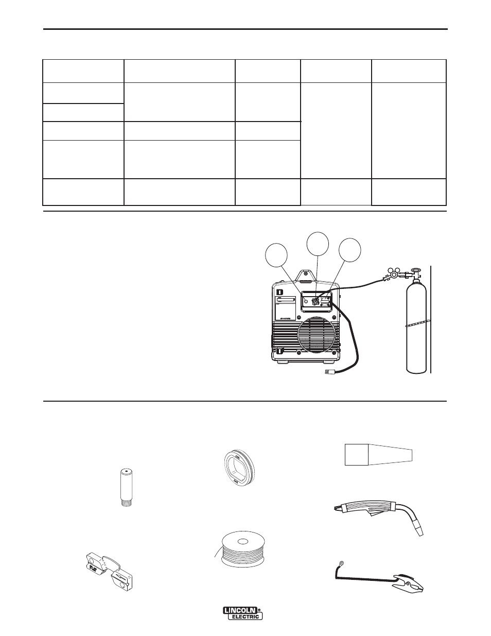
A. ITEMS NEEDED FOR
FLUX CORED WELDING
1. 035”(0.9mm) Contact Tip
2. .025”-.035”(0.6mm-0.9mm) wire
guide
3. Knurled Drive Roll
4. .035”(0.9mm) NR-211MP Flux-
Cored Wire
5. Black Flux Cored gun nozzle
6. Welding Gun
7. Work Cable & Clamp
.035
.035 NR-211 MP
FLUX-CORED WIR
E
SETTING UP AND MAKING A FLUX-CORED WELD
B-4
OPERATION
B-4
POWER MIG® 180 DUAL
(See Figure B.6 for the following Items.)
12. CIRCUIT BREAKER – If the rated input current of
the machine is exceeded this circuit breaker will
trip. Press to reset.
13. GAS INLET – Shielding gas connects to this inlet.
14. POWER CORD CONNECTION - Ensure power
cord is diconnected from input voltage supply prior
to connecting or removing the cord from the
machine. Connect the circular connector present
on either input cord (120V or 230V) to the recepta-
cle on the back of the machine. The power cord
connector is secured to the receptacle by rotating
the connectorʼs coupling ring clockwise, until the
coupling ring latches on to the receptacle. Use
only the appropriate (120V or 230V) power cords
supplied by the Lincoln Electric Company.
12
13
14
FIGURE B.6
TABLE B.1
DRIVE ROLL AND WIRE GUIDES
Wire Diameter &
Type
.025”(0.6mm) MIG wire
.030”(0.8mm) MIG wire
.035”(0.9mm) MIG wire
.030”(0.8mm) flux-cored
.035”(0.9mm) flux-cored
.045”(1.1mm) flux-cored
Drive Roll
.025”/.030” (0.6mm/0.8mm)
Smooth Drive Roll
.035”(0.9mm) Smooth Drive Roll
.030”/.045” (0.8mm/1.1mm)
Knurled Drive Roll
.030”/.045” (0.8mm/1.1mm)
Knurled Drive Roll
Inner Wire Guide
.025”-.035”
(0.6mm-0.9mm)
Steel Wire Guide
.045”(1.1mm) Steel
Wire Guide
Inner Wire Guide
Part Number
KP2531-1
KP2531-2
Drive Roll Part
Number
KP2529-1
KP2529-2
KP2529-3
KP2529-3
INNER WIRE GUIDE
.025-.035 (.6-.9mm)