Operation, Auxiliary power – Lincoln Electric IM10003 VANTAGE 500-I User Manual
Page 22
AUXILIARY POWER:
Start the engine and set the IDLER control switch to
the desired operating mode. Full power is available
regardless of the welding control settings providing no
welding current is being drawn.
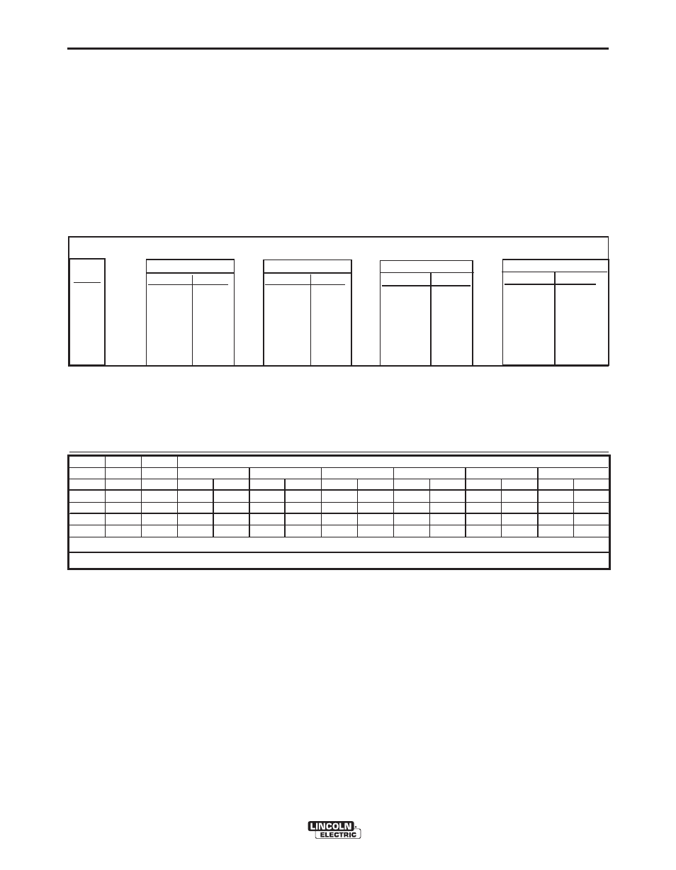
Simultaneous Welding and Auxiliary Power Loads
The auxiliary power ratings are with no welding load.
Simultaneous welding and power loads are specified
in the following Table B.4.
Weld
Amps
0
100
200
300
400
500
1 PHASE (120V)
WATTS AMPS
4200 35
4200 35
4200 35
4200 35
1700 14
0 -
1 PHASE (240V)
WATTS AMPS
3600 15
3600 15
3600 15
3600 15
1700 7
0
3 PHASE
WATTS AMPS
17,000 41
15,400 37
13,000 31
9400 23
3400 8
0 0
BOTH 1 & 3 PHASE
WATTS AMPS
- 50
- 50
- 50
4,700 -
1,700 -
0 -
VANTAGE® 500-I Simultaneous Welding and Power Loads
PLUS
OR
OR
OR
VANTAGE® 500-I
b-7
OPERATION
b-7
TAbLE b.4
VANTAGE® 500-I Extension Cord Length Recommendations
(Use the shortest length extension cord possible sized per the following table.)
Current
(Amps)
15
20
15
20
44
Voltage
Volts
120
120
240
240
240
Load
(Watts)
1800
2400
3600
4800
9500
30
60
(9)
(18)
40
30
75
60
(12)
(9)
(23)
(18)
75
50
150
100
50
(23)
(15)
(46)
(30)
(15)
125
88
225
175
90
(38)
(27)
(69)
(53)
(27)
175
138
350
275
150
(53)
(42)
(107)
(84)
(46)
300
225
600
450
225
(91)
(69)
(183)
(137)
(69)
Maximum Allowable Cord Length in ft. (m) for Conductor Size
Conductor size is based on maximum 2.0% voltage drop.
14 AWG
12 AWG
10 AWG
8 AWG
6 AWG
4 AWG
TAbLE b.5