Operation, B-8 auxiliary power operation – Lincoln Electric IM10053 RANGER 305 D (AU) User Manual
Page 23
B-8
OPERATION
B-8
AUXILIARY POWER OPERATION:
Start the engine and set the IDLER control switch to
the desired operating mode. Full power is available
regardless of the welding control settings, if no weld-
ing current is being drawn.
The auxiliary power of the Ranger® 305D (AU) con-
sists of two 15Amp 240VAC single phase receptacles.
The auxiliary power receptacles should only be used
with three wire grounded type plugs or approved dou-
ble insulated tools with two wire plugs.
The current rating of any plug used with the system
must be at least equal to the current capacity of the
associated receptacle.
NOTE: The 240 V receptacle has two circuits, each of
which measure 120 V to neutral but are of opposite
polarities and cannot be paralleled.
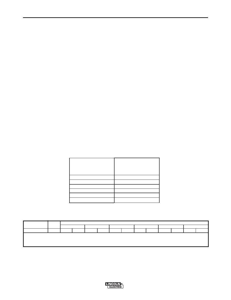
Simultaneous Welding and Auxiliary Power Loads
The above auxiliary power ratings are with no welding
load. Simultaneous welding and power loads are
specified in the following table:
RANGER® 305D (AU)
Welding
Output-Amps
0
100
150
200
250
300
Permissible Power-Watts
(Unity Power Factor)
7200
7200
5600
4200
2300
0
* Each receptacle is limited to 15 amps.
Ranger® 305D (AU) Simultaneous Welding and Power Loads
Ranger® 305D (AU) Extension Cord Length Recommendations
(Use the shortest length extension cord possible sized per the following table.)
Current
(Amps)
15
Voltage
Volts
240
Load
(Watts)
3600
60
(18)
75
(23)
150
(46)
225
(69)
350
(107)
600
(183)
Maximum Allowable Cord Length in ft. (m) for Conductor Size
Conductor size is based on maximum 2.0% voltage drop.
14 AWG
12 AWG
10 AWG
8 AWG
6 AWG
4 AWG