Accessories, C-13 – Lincoln Electric IM10024 MAXsa 22_29 Wire Drive User Manual
Page 37
C-13
ACCESSORIES
MAXsa™ 22 & 29 WIRE DRIVES
C-13
K225 SUBMERGED ARC TWINARC
®
KIT
Twin arc welding is a process where two wires of the
same size are fed through a nozzle by a single wire
drive. The K225 Twinarc Kit can be used to weld with
5/64”, 3/32” or 1/8” (2.0, 2.4 or 3.2mm) electrodes.
Both wires must be the same size.
The gear ratio of the MAXsa™ 22 & 29 WIRE DRI-
VES as shipped is 142:1. This may not provide
enough wire speed for the procedure. Gears for 95:1
or 57:1 ratio are also shipped with the MAXsa™ 22 &
29 WIRE DRIVES units. See the instructions in this
manual to change the gear ratio.
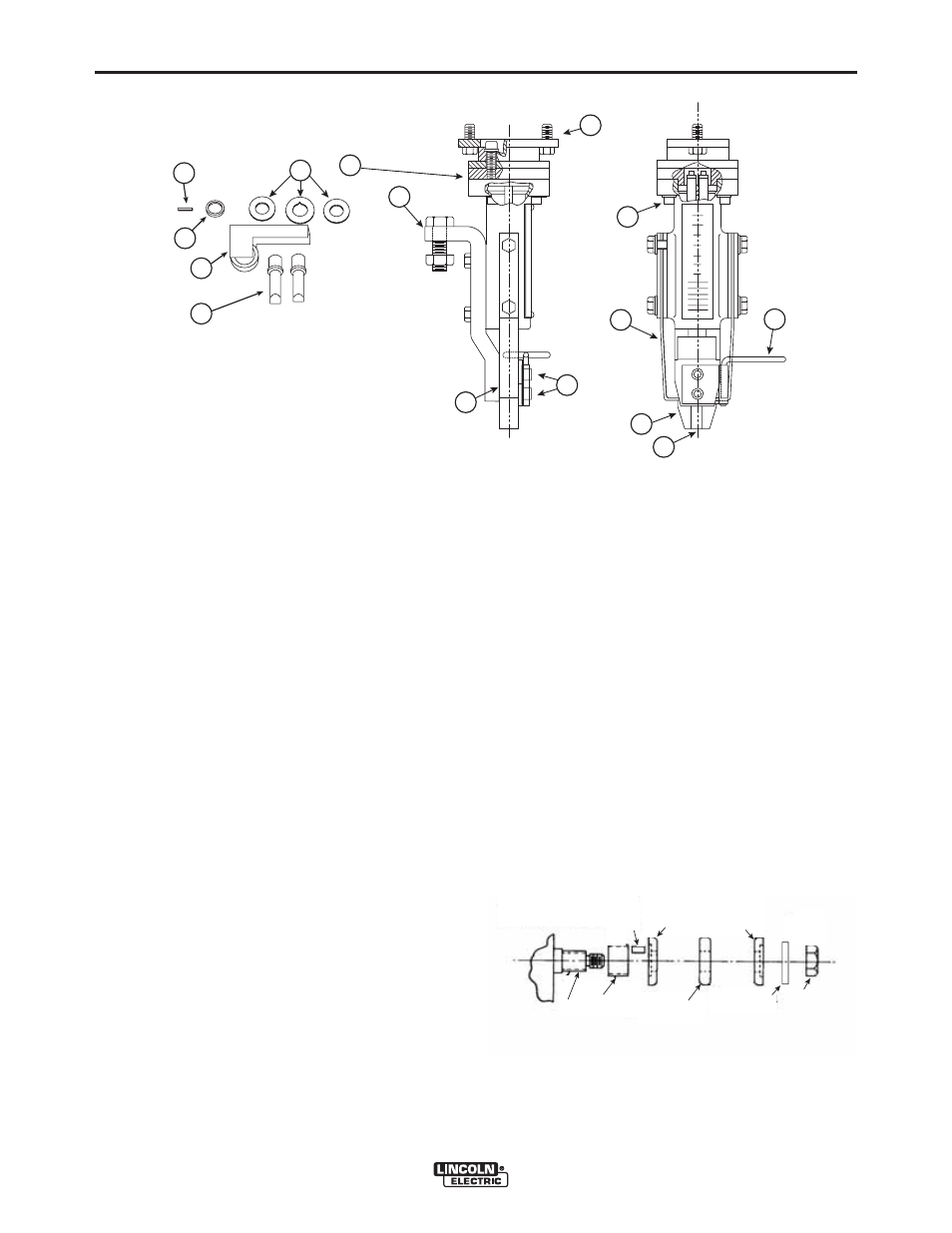
Each assembly comes with a wire reel, a reel brake,
shaft and mounting bracket, a dual wire straightener
and all of the wire drive components for the particular
wire size. See Figure C.18.
The Nozzle Assembly (F) has two spring loaded large
copper jaws (6) that press the electrodes against the
copper center block (4). This system provides good
electrical contact and insures constant electrical stick-
out (E.S.O.) It also helps to maintain acceptable noz-
zle temperatures during welding.
INSTALLATION
1. Remove the following items from the standard
Feed Head.
• The wire straightener.
• The nozzle assembly.
• Both upper and lower guide tubes.
• The drive rolls.
• The idle roll assembly.
NOTE: The idle roll arm pivot pin is held in place by a
set screw that is accessed from the outgoing
surface of the faceplate.
• The tension spring assembly.
• The Drive Roll Spacer.
NOTE: The set screw that holds the drive roll spacer
in place is accessible once the idle roll assem-
bly is removed.
2. Oil or grease the O.D. of the new shorter drive
roll spacer (E) and place it on the output shaft.
Push it back as far as it will go and tighten the
set screw.
3. Place the new longer key (F) in the keyway.
4. Place the outer, center and second outer drive
rolls (A) on the shaft. Replace the clamping
washer and the locking nut and tighten securely.
See Figure C.19.
FIGURE C.18 - K225 TWINARC
®
COMPONENTS
C
B
A
D
E
A - Drive Rolls
B - Guide Tubes
C - Idle Roll Arm
D - Drive Roll Spacer
E - Key
F - Nozzle Assembly
1
2
7
5
9
6
4
3
8
F
FIGURE C.19
Output
Shaft
Drive Roll
Spacer
Key
Outer Drive Rolls
Center
Drive Roll
Clamping
Washer
Locking
Nut