Gun lead connections, Coolant connections, Gun tube removal/ installation – Lincoln Electric IM10168 K3355-,K3356-,K3357-,K3358- MAGNUM PRO AL Push Pull Gun User Manual
Page 9
A - 2
INSTALLATION
MAGNUM
®
PRO AL Gun
GUN LEAD CONNECTIONS
POWER CABLE
Air Cooled
A #2 power cable is used on the
Lincoln Electric Magnum
®
Pro
AL Gun.
• The gun and Power Pin ends are threaded into the gun body.
• These connections utilize a conductive sealant and are
tightened with torque requirements of 100 + 5 IN-LB.
Water Cooled
• Lincoln
Electric Magnum
®
Pro AL Gun
water cooled gun
utilizes a power/water cable with a #6 AWG cable inside a
5/16” diameter hose.
• When water is used with this cable and the #10 water cooled
gas nozzle (P/N KP3375-1), the system is rated at 450 amps
@ 60% duty cycle.
• The gun end is threaded into the gun body.
•
These connections utilize a conductive sealant and are
tightened with torque requirements of 100 + 5 IN-LB.
CONDUIT
•
The Lincoln Electric Magnum
®
Pro AL Gun comes standard
with a poly-lined conduit, for feeding aluminum wire.
•
end.
• Both ends
of the conduit are secured into the Power Pin
connector with a set screw.
GAS HOSE
•
end of the gun body and secured by twisting the hose retainer
to the end of the hose (shown below).
• The opposite end of the BLACK hose is pushed over a
• The hose retainer is re-usable and can be removed and
re-installed as needed.
CONTROL CABLE
•
A multi-conductor control cable is used on the Lincoln Electric
Magnum
®
Pro AL Gun 7 and 12 pin.
COOLANT CONNECTIONS
•
T
he ends of the coolant hose push
the end of the rear connector and are secured by twisting the
hose retainer to the end of the hose.
• The hose retainer is re-usable and can be removed and
re-installed as needed.
• The BLUE coolant supply hose pushes over a
and is secured by twisting the hose retainer to the end of the
hose.
• The opposite end of the BLUE hose pushes into a threaded
•
in the Power Manifold.
• The opposite end of the RED hose pushes into a threaded
return hose of the coolant recirculator.
•
hoses are standard left-hand thread.
COOLANT RECOMMENDATIONS
• Use coolant (Aluminum protection),which does not contain
reactive sulphur or chlorine and does not react with copper,
brass or aluminum.
• Coolant is available in quantities of 1 gallon, 5 gallon (P/N
KP3379-1), or a case of 4 gallons each (P/N KP3379-4).
•
(1 qt/min) between 35 and 45psi. Contact the re-circulator
•
pressure.
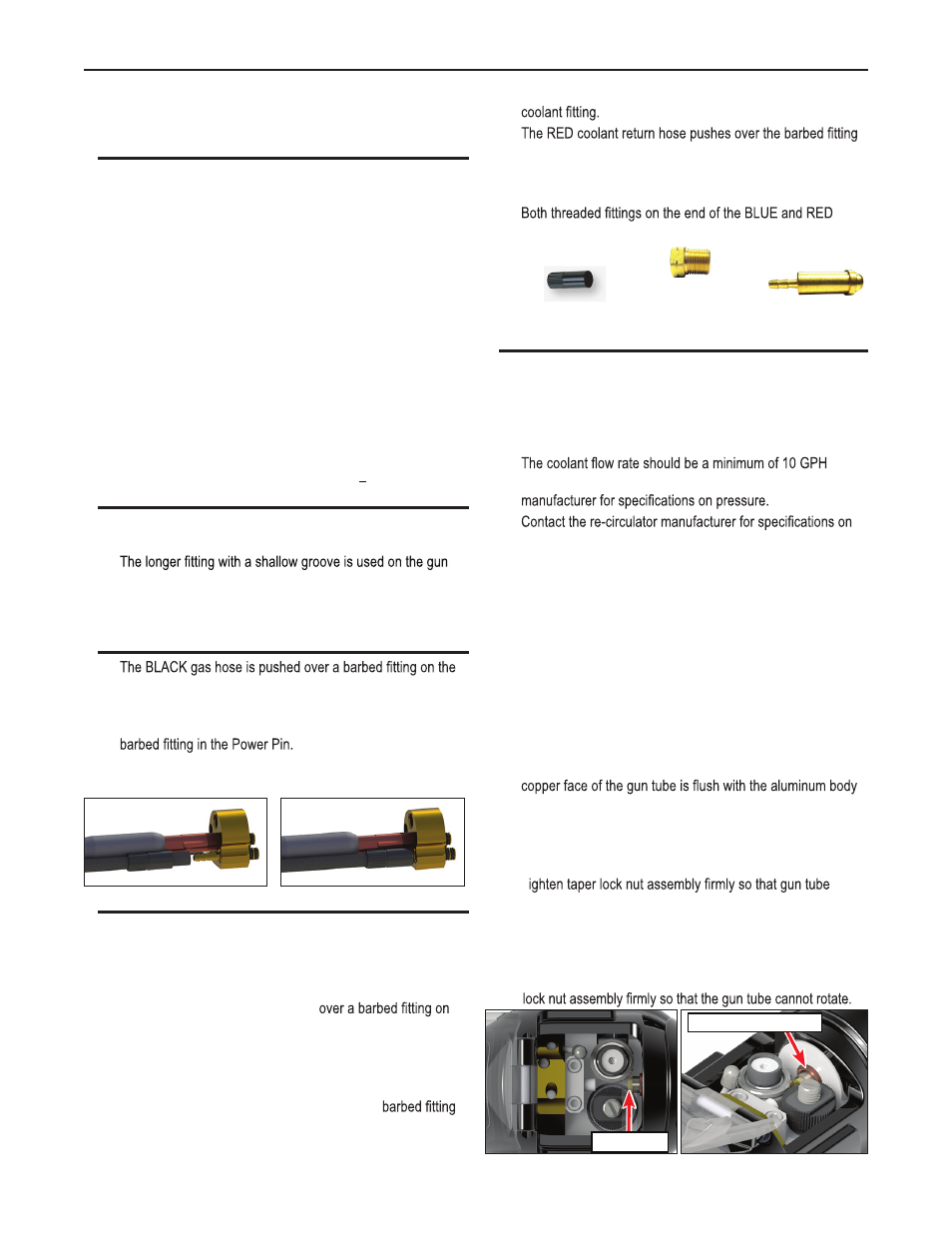
GUN TUBE REMOVAL/
INSTALLATION
WARNING: Do not attempt to weld without the gun tube being
tightly secured in the gun body, or damage to the gun tube or
body may result.
a. To remove the gun tube assembly, loosen the taper lock nut until
it is clear of the threads. Pull gun tube out of the gun body.
b. To replace a gun tube assembly, open the drive and idler roll
door and seat the gun tube assembly until the plastic liner is
almost touching the drive and idler roll (Figure 1) and the rear
block (Figure 2).
c. Take care not to damage the “O” rings when inserting into the
body. You should hear an audible "click" when the gun tube is
inserted and seated.
d. T
cannot rotate.
Gun Tube Rotation
a. To rotate a gun tube assembly, loosen the taper lock nut
assembly no more than 1 turn.
b. Rotate gun tube to the position of your choice and retighten taper
S29830-97*
Left-Hand Threaded Fitting
*Must be ordered together
S29830-14
5/16” Hose Retainer
S29830-96*
Nipple
Copper face of gun tube
Plastic liner
Figure 2
Figure 1