General description – Lincoln Electric IM10168 K3355-,K3356-,K3357-,K3358- MAGNUM PRO AL Push Pull Gun User Manual
Page 11
B - 1
OPERATION
MAGNUM
®
PRO AL Gun
GENERAL DESCRIPTION
The Lincoln Electric Magnum
®
Pro
AL Gun
gun maintains a
constant, steady, uniform wire feed speed. The constant push
exerted by the motor in the cabinet, combined with the pull of the
the wire conduit. The 24VDC gun motor is controlled by a three
and three-quarter (3 3/4) turn potentiometer in the gun handle.
CONTROLS AND SETTINGS
Potentiometer:
• The laterally-positioned potentiometer is located in the gun
body, providing up to 800 ipm with 3 3/4 turns.
Micro Switch:
• The micro switch assembly consists of the micro switch, and
leads.
Trigger Sensitivity:
• The amount of trigger level travel can be shortened for a
"quicker" or "more responsive" action.
• A more sensitive trigger lever is produced by reducing the
gap between the trigger lever and the micro switch lever.
• By turning-in the Trigger Sensitivity Adjustment Screw, it
closes the gap between the trigger lever and the micro switch
lever - this enables the operator to increase the sensitivity of
the trigger lever.
Sensitivity Adjustment:
• With the wire feeder turned on (with or without welding wire
loaded), turn the screw in until the micro switch is activated.
• Once activated, the gun and wire feeder motors will begin
feeding wire.
• Retract the screw accordingly until the system is deactivated
and adjusted to the operators' liking.
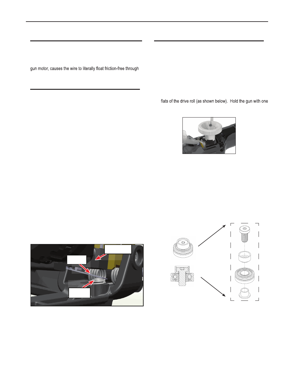
DRIVE ROLL AND IDLER ROLLS
Drive Roll Installation and Removal:
NOTE: Neither of the handles needs to be removed to access
the Drive or Idler Rolls.
1. Pull the Cam Lever away from the idler roll. This will relieve
the pressure against the drive roll.
2. Align the Drive Roll Removal Tool (P/N K3987-1) over the
hand or on a table top, with the other hand give the Removal
Tool a quick snap-turn in the CLOCKWISE DIRECTION.
3. Once the drive roll is loose, continue to spin drive roll in the
clockwise direction to remove the drive roll from the gun.
4. Install a new drive roll on the left-hand threaded shaft. The
drive roll will self-tighten when it is feeding wire.
Idler Roll Installation and Removal:
Please use the following drawing as a guide when needing to
reassemble prior to installing into the welding gun.
Screw adjusted out of trigger, pre-setting the micro switch lever for
shorter trigger motion sensitivity.
Set Screw
Lever
Micro Switch