Installation, Warning, Control cable set-ups – Lincoln Electric IM10079 LN-25 PRO DUAL POWER User Manual
Page 18
A-9
INSTALLATION
LN-25™ PRO DUAL POWER
A-9
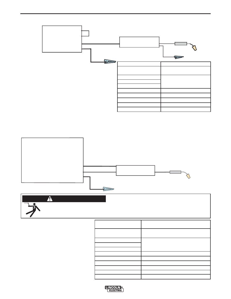
CV Power Source with Twist-Mate Connectors and
no Remote/Local Switch. (See Figure A.9)
Place CV/CC switch in the feeder in the "CV" position.
CV-250
CV-300
Work
Electrode
Jump er
W or k clip
LN-25™ PRO DUAL POWER
FIGURE A.9
K#
K2614-6, -8
KP1695-XX
KP1696-XX
KP1697-XX
See Magnum Literature
K1841-XX
K852-95
K484
Description
LN-25™ PRO Dual Power,
PRO Dual Power European
Drive Roll Kit
Welding Gun
CV power Source
Welding Cables
Twist-Mate Cable Plug
Jumper Plug kit
CONTROL CABLE SET-UPS
CV Power Source with 24-42 VAC
(See Figure A.10)
If present, place the power source
Remote/Local Switch in the Remote posi-
tion.
Place CV/CC switch in the feeder in the
"CV" position.
CV Power Source
CV-305
CV-400
CV-655
DC-400
DC-655
V-350
V-450
Work
Electrode
Control Cable
VANTAGE 300, 400, 500
RANGER 250, 305
ENGINE DRIVE WITH
WIRE FEED MODULE
SAE’s WITH K385-2
LN-25™ PRO DUAL POWER
K#
K2614-6, -8
KP1695-XX
KP1696-XX
KP1697-XX
K1797-xx
K2335-1
See Magnum Literature
KP1803-XX
K852-95
Description
LN-25™ PRO Dual Power,
PRO Dual Power European
Drive Roll Kit
Control Cable
Adapter for Competitive Power Sources
Welding Gun
CV power source
Welding Cables
Twist-Mate Cable Plug
FIGURE A.10
ELECTRIC SHOCK CAN KILL.
• When the wire feeder is connected to the power source with the control cable, the
contactor in the wire feeder is always closed and the wire drive and the gun may be at
welding potential.
WARNING