Installation, Warning – Lincoln Electric IM10076 LN-25 PRO User Manual
Page 15
THUMB
SCREW
GUN
A-6
INSTALLATION
LN-25™ PRO
A-6
GuN CONNECTION
ELECTRIC ShOCK can kill.
• Turn the input power OFF at the weld-
ing power source before installation or
changing drive rolls and/or guides.
• Do not touch electrically live parts.
• When inching with the gun trigger, electrode
and drive mechanism are "hot" to work and
ground and could remain energized several sec-
onds after the gun trigger is released.
• Do not operate with covers, panels or guards
removed or open.
• Only qualified personnel should perform mainte-
nance work.
------------------------------------------------------------------------
The LN-25™ PRO comes with a K1500-2 gun adapter
installed. (See Figure A.4)
To install a gun,
1. Turn power OFF.
2. Remove the thumb screw.
3. Push the gun the completely into the gun bushing.
4. Secure the gun in place with the thumb screw.
5. Connect the trigger cable from the gun to the trigger
connector on the front of the feeder.
Note: Not all gun bushings require the use of the
thumb screw.
FIGuRE A.4
WARNING
PRESSuRE ARM and ADJuSTMENT
ELECTRIC ShOCK can kill.
• Turn the input power OFF at the
welding power source before instal-
lation or changing drive rolls and/or
guides.
• Do not touch electrically live parts.
• When inching with the gun trigger, electrode
and drive mechanism are "hot" to work and
ground and could remain energized several sec-
onds after the gun trigger is released.
• Do not operate with covers, panels or guards
removed or open.
• Only qualified personnel should perform mainte-
nance work.
------------------------------------------------------------------------
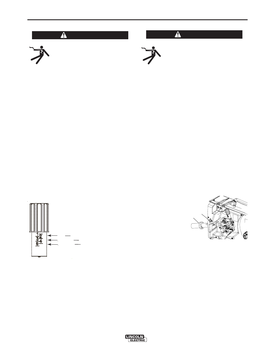
The pressure arm controls the amount of force the
drive rolls exert on the wire. Proper adjustment of the
pressure arm gives the best welding performance.
Many welding problems can be attributed to setting
the pressure arm too high and causing wire deforma-
tion. Set the pressure arm to minimum amount that
provides reliable feeding.
Set the pressure arm as follows:
(See Figure A.3)
Aluminum wires
between 1 and 2
Cored wires
between 1 and 3
Steel, Stainless wires
between 3 and 5
FIGuRE A.3
WARNING
6
Al
FCAW
GMAW
ALUMINUM WIRES
CORED WIRES
STEEL, STAINLESS WIRES