Helmet care and maintenance, Shade guide settings – Lincoln Electric IM10146 MARQUETTE AUTO-DARKENING HELMET User Manual
Page 6
HELMET CARE AND MAINTENANCE
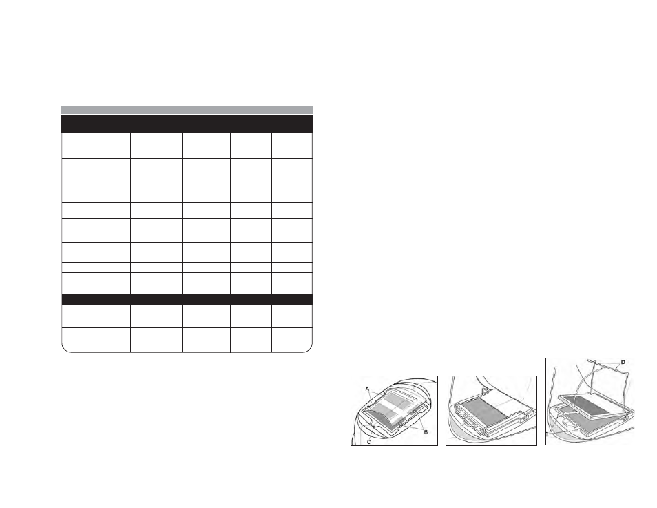
Replacing Front Cover Lens: Replace the front cover lens if it is damaged
– cracked, soiled or pitted. Place your finger or thumb into recess (C) at the
bottom edge of the cover lens and flex the lens upwards until it releases from
the edges marked A and B. (Refer to figure 1).
Replace the Inside Cover Lens: if it is damaged (cracked, soiled or pitted).
Place your fingernail in recess above cartridge view window and flex lens
upwards until it releases from edges of cartridge view window.
Change the Shade Cartridge (See figure 2)
Fitting New Cartridge: Take the new shade cartridge and pass the poten-
tiometer cable under the wire loop before placing the cartridge into its retain-
ing frame inside the helmet. Hinge down the wire loop and ensure the front
edge of the loop (D) is properly retained under the retaining lugs (E) as
shown in (figure 3).
Position the shade potentiometer to the inside of the helmet with the shaft
protruding through the hole. Secure potentiometer to shell. On the outside of
the helmet, push the shade control knob onto the shaft.
Cleaning: Clean helmet by wiping with a soft cloth. Clean cartridge surfaces
regularly. Do not use strong cleaning solutions. Clean sensors and solar cells
with soapy water solution and a clean cloth and wipe dry with a lint-free cloth.
Do NOT submerge shade cartridge in water or other solution.
Storage: Store in a clean, dry location.
5
Figure 1
Figure 2
Figure 3
ALWAYS TEST TO BE SURE THE ADF CARTRIDGE IS CHARGED
BEFORE WELDING. The helmet can be placed in sunlight to charge. Do
not store the helmet in a dark cabinet or other storage area for long periods.
While welding, the arc also charges the ADF cartridge.
SHADE GUIDE SETTINGS
If your helmet does not include any one of the shades referenced above, it is
recommended you use the next darker shade.
4
GUIDE FOR SHADE NUMBERS
OPERATION
ELECTRODE SIZE
ARC
MINIMUM
SUGGESTED(1)
1/32 in. (mm)
CURRENT (A)
PROTECTIVE
SHADE NO.
SHADE
(COMFORT)
Shielded metal arc
Less than 3 (2.5)
Less than 60
7
–
welding
3-5 (2.5–4)
60-160
8
10
5-8 (4–6.4)
160-250
10
12
More than 8 (6.4)
250-550
11
14
Gas metal arc
Less than 60
7
–
welding and flux
60-160
10
11
cored arc welding
160-250
10
12
250-500
10
14
Gas tungsten arc
Less than 50
8
10
welding
50-150
8
12
150-500
10
14
Air carbon
(Light)
Less than 500
10
12
Arc cutting
(Heavy)
500-1000
11
14
Plasma arc welding
Less than 20
6
6 to 8
20-100
8
10
100-400
10
12
400-800
11
14
Plasma arc cutting
(Light)
(2)
(2)
(2)
Less than 300
8
9
(Medium)
300-400
9
12
(Heavy)
400-800
10
14
Torch brazing
–
–
3 or 4
Torch soldering
–
–
2
Carbon arc welding
–
–
14
PLATE THICKNESS
in.
mm
Gas welding
Light
Under 1/8
Under 3.2
4 or 5
Medium
1/8 to 1/2
3.2 to 12.7
5 or 6
Heavy
Over 1/2
Over 12.7
6 or 8
Oxygen cutting
Light
Under 1
Under 25
3 or 4
Medium
1 to 6
25 to 150
4 or 5
Heavy
Over 6
Over 150
5 or 6
(1)
As a rule of thumb, start with a shade that is too dark, then go to a lighter shade which gives sufficient view of the weld zone without going
below the minimum. In oxyfuel gas welding or cutting where the torch produces a high yellow light, it is desirable to use a filter lens that absorbs
the yellow or sodium line the visible light of the (spectrum) operation
(2)
These values apply where the actual arc is clearly seen. Experience has shown that lighter filters may be used when the arc is hidden by the
workpiece.
.
Data from ANSI Z49.1-2005