Connection of ln-7 t o the dc-600 vrd power source, Diagrams, Idealarc – Lincoln Electric IM10018 IDEALARC DC-600 VRD User Manual
Page 46: Dc-600 vrd
F-6
DIAGRAMS
F-6
IDEALARC
®
DC-600 VRD
N.C.
T
ape
up
bo
lted
connection
if
l
ead
#21
is
e
x
tended.
N.D.
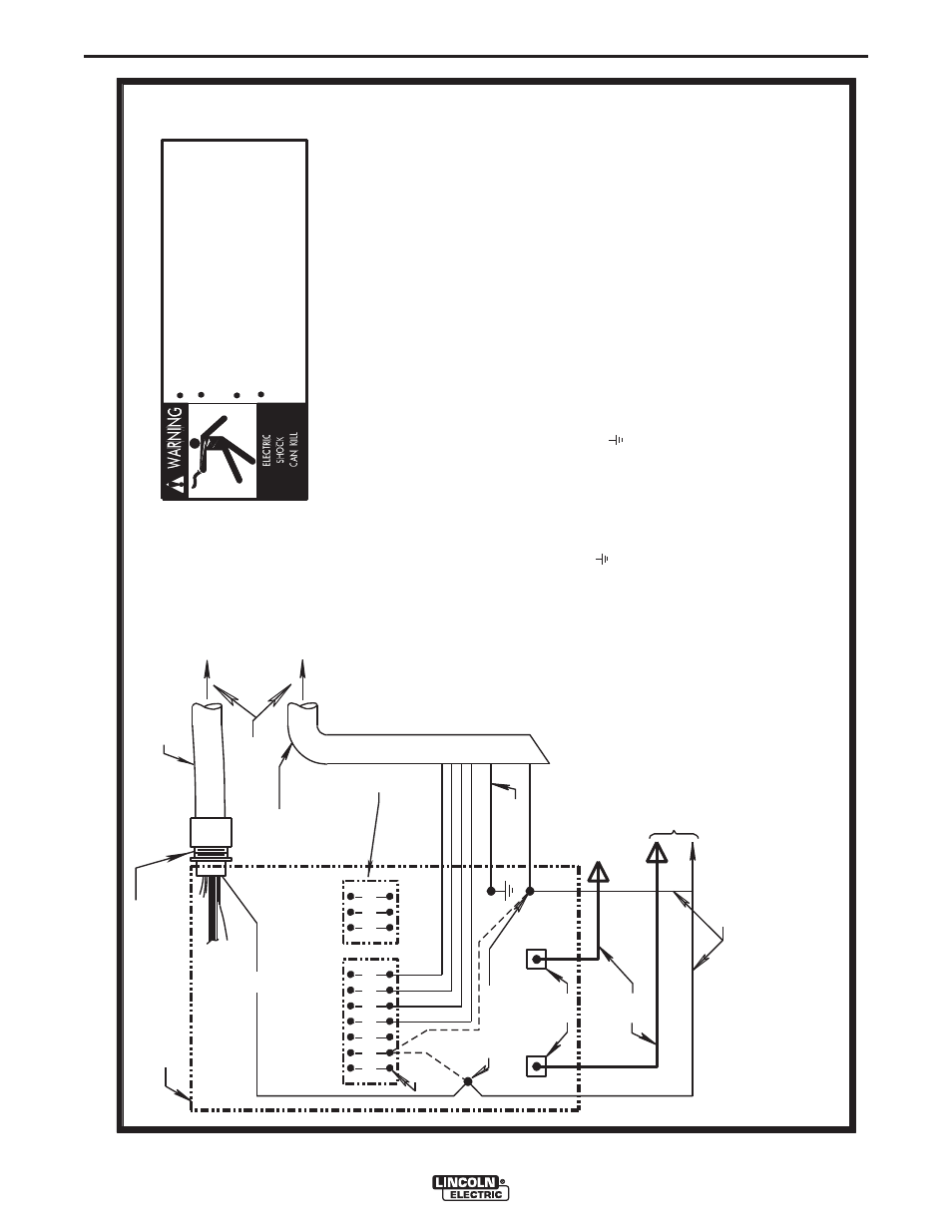
Connect
the
contro
l
cab
le
ground
l
ead
to
the
frame
termina
l
marked
near
the
power
source
termina
l
strip.
The
power
source
grounding
termina
l
(marked
and
l
ocated
near
the
power
source
input
power
connections)
must
be
proper
ly
connected
to
e
lectrica
l
ground
per
the
power
source
operating
manua
l.
N.E.
I
f
an
optiona
l
remote
vo
ltage
contro
l
is
used,
connect
it
to
this
termina
l
strip.
N.A.
We
lding
cab
les
must
be
of
proper
capacity
for
the
current
and
duty
cyc
le
of
immediate
and
future
app
lications.
See
LN-7
Operating
Manua
l
for
proper
sizes.
N.B.
I
f
LN-7
is
equipped
with
a
meter
kit,
e
x
tend
LN-7
contro
l
cab
le
suitab
le
for
the
insta
ll
ation.
An
S16586-
[LENGTH
]
remote
vo
ltage
sensing
work
l
ead
may
be
ordered
for
this
purpose.
Connect
it
direct
ly
to
the
work
piece
independent
of
the
we
lding
work
cab
le
connection.
For
convenience,
this
e
x
tended
#21
l
ead
shou
ld
be
taped
to
the
we
lding
work
l
ead.
(I
f
the
l
ength
of
we
lding
work
cab
le
is
short,
l
ess
than
25
feet,
and
connections
can
be
e
x
pected
to
be
re
liab
le,
then
contro
l
cab
le
l
ead
#21
does
not
need
to
be
e
x
tended
and
can
be
direct
ly
connected
to
termina
l
#21
on
the
termina
l
strip.
Note
that
this
is
not
the
preferred
connection
because
it
adds
error
to
the
LN-7
vo
ltmeter
Above
diagram
shows
e
lectrode
connected
positive.
To
change
po
larity
,
turn
power
of
f,
reverse
the
e
lectrode
and
work
l
eads
at
the
power
41
423
1
32
75
76
77
NEGA
T
IVE
POS
IT
IVE
32
31
2
4
GND
21
N.A.
N.D.
ELECTRODE
CABLE
TO
W
IRE
FEED
UN
IT
TO
WORK
POWER
SOURCE
N.E.
N.F
.
reading.)
N.F
.
I
f l
ead
#21
is
to
be
connected
to
the
termina
l
strip,
connect
to
the
#21
termina
l
that
matches
work
po
larity
.
This
connection
must
be
changed
whenever
the
e
lectrode
po
larity
is
changed.
Only qualified persons should install, use or
service this machine.
Do not operate with covers removed.
Disconnect power source before
servicing.
Do not touch electrically live parts.
LN-7
TO
I
NPUT
CABLE
PLUG
LN-7
CONTROL
CABLE
21
-
21
FOR
CONTROL
CABLE
W
ITH
14
P
IN
MS-T
Y
PE
PLUG
CONNECT
OR
OR
FOR
CONTROL
CABLE
W
ITH
TERM
INAL
STR
IP
LEAD
CONNECT
ORS
CONTROL
CABLE
S22976
source
and
position
the
switch
on
wire
feeder
(if
equipped
)
to
proper
po
larity
.
A
lso
refer
to
note
N.F
.
N.B.
&
N.C.
14-P
IN
RECEPT
ACLE
lead
#21
from
contro
l
cab
le
with
termina
l
strip
connectors
or
from
14-pin
receptac
le
using
#14
AW
G
or
l
arger
insu
lated
wire
physica
ll
y
21
+
REMOTE
VOL
T
AGE
SENS
ING
LEAD
10-30-98F
N.G.
N.G.
Ill
ustration
does
not
necessari
ly
represent
actua
l
position
of
for
more
information.
CONNECTION OF LN-7 T
O THE DC-600 VRD POWER SOURCE
appropriate
output
studs.
Refer
to
power
source
operating
manua
l
For
proper
setting
of
switches
on
power
source,
see
power
source
operating
manua
l.