2 panel mounting, Figure 5-19: cutout dimensions – IEI Integration AFL2-17A-H61 v1.23 User Manual
Page 84
AFL2-17A/AB-H61
P a g e 64
5.13.2 P a n e l Mo u n tin g
To mount the AFL2-17A/AB-H61 flat bezel panel PC into a panel, please follow the steps
below.
S te p 1:
Select the position on the panel to mount the flat bezel panel PC.
S te p 2:
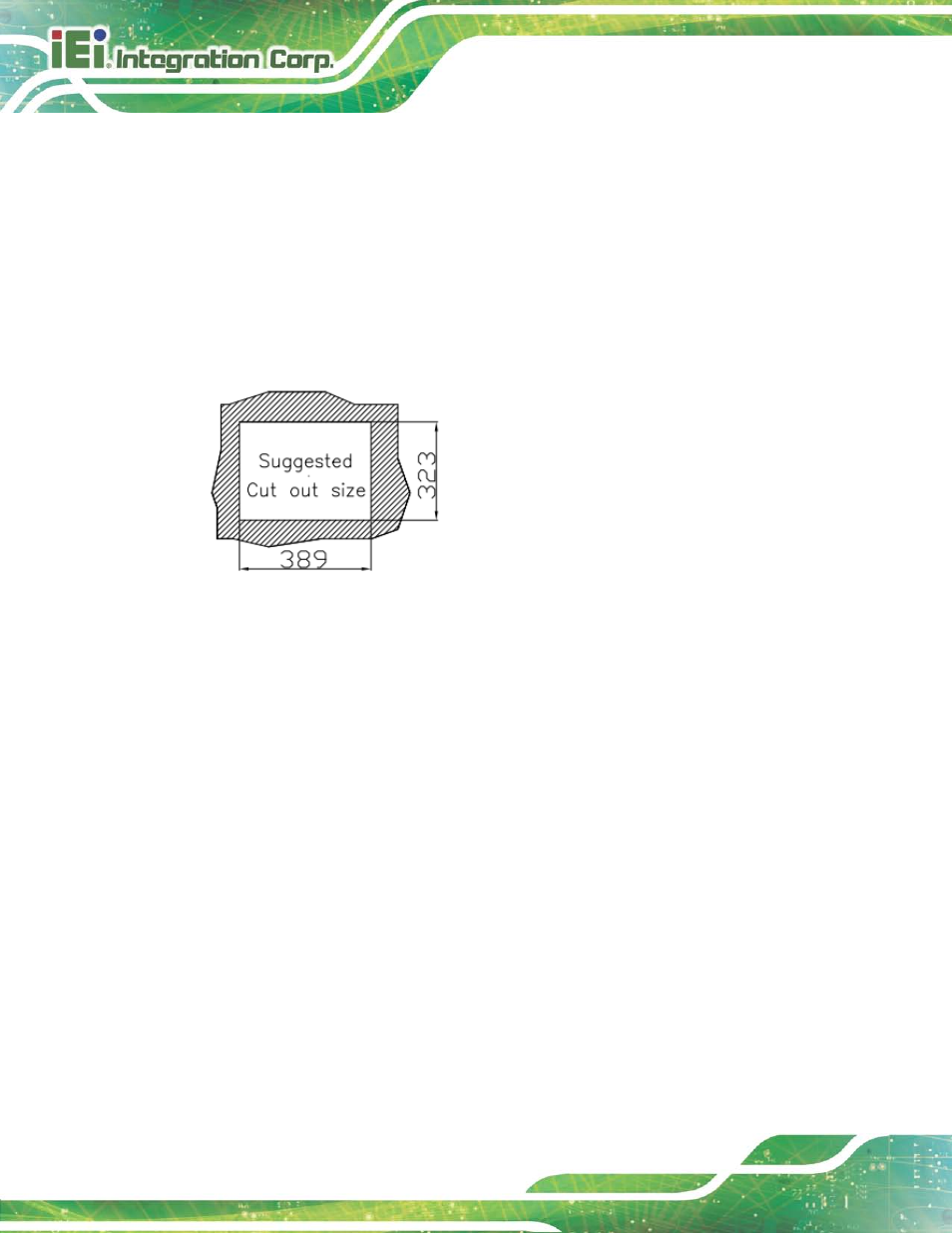
Cut out a section corresponding to the size shown below. The size must be
smaller than the outer edge.
Figure 5-19: Cutout Dimensions
S te p 3:
Slide the flat bezel panel PC through the hole until the frame is flush against the
panel.
S te p 4:
Align the panel mounting bracket screw holes with the VESA mounting holes on
the rear of the panel PC.
S te p 5:
Secure the two panel mounting brackets to the rear of the panel PC by inserting
the four retention screws into the VESA mounting holes (Figure 5-20
).
S te p 6:
Insert the panel mounting clamps into the holes of the panel mounting brackets
). There are a total of 4 panel mounting clamps for
AFL2-17A/AB-H61.
S te p 7:
Tighten the screws that pass through the panel mounting clamps until the plastic
caps at the front of all the screws are firmly secured to the panel.