Front panel cable connections – IEI Integration EBC-3000 User Manual
Page 5
EBC-3000 IEI Technology Corp. Page 5
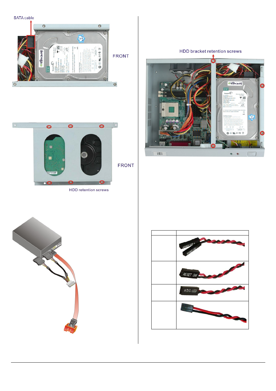
Figure 7: HDD Bracket (Top)
Step 2:
Attach the HDD to the HDD bracket. Align the
retention screw holes in the sides of the bracket
with the retention screw holes on the HDD. Insert
the retention screws into the bracket as seen below.
Figure 8: HDD Retention Screws
Step 3:
Attach SATA and power cable to HDD and SBC as
shown below according to the SBC user manual.
Figure 9: SATA Cables
Step 4:
Install the bracket with HDD into the chassis by
aligning the bracket retention screw holes in the top
of the HDD bracket with the retention screw holes
on the chassis. Insert the four previously removed
retention screws into the top of the HDD bracket
(Figure 10).
Figure 10: HDD/ODD Bracket Retention Screws
FRONT PANEL CABLE CONNECTIONS
The following buttons and LEDs are on the front panel of the EBC-3000
chassis.
1 x Power LED
1 x HDD LED
1 x Power switch
1 x Reset button
These components are all connected to the SBC with cables. To correctly
connect these cables, please refer to the technical documentation that
came with your SBC. The connectors that are provided with the chassis
are listed below.
No. Name
1
Power LED cable
1
Reset Switch cable
1
HDD LED cable
1
Power switch cable
Table 6: Chassis Connectors