Step 4: cf module installation (optional), Step 5: disk drive installation – IEI Integration EBC-3200 User Manual
Page 4
EBC-3200 QIG IEI Technology Corp. Page 4
retention screws.
Step 7:
Reinstall the two brackets removed in Step 1 and
Step 2.
Step 0:
STEP 4: CF MODULE INSTALLATION
(OPTIONAL)
To install the optional CF module, please follow the steps
below.
Step 1:
Remove the expansion slot bracket.
Step 2:
Mount the CF module onto the HDD bracket. To
do this, align the four retention screw holes in the
CF module with the retention screw holes in the
HDD bracket.
Step 3:
Insert the four retention screws to secure the CF
module with the bracket.
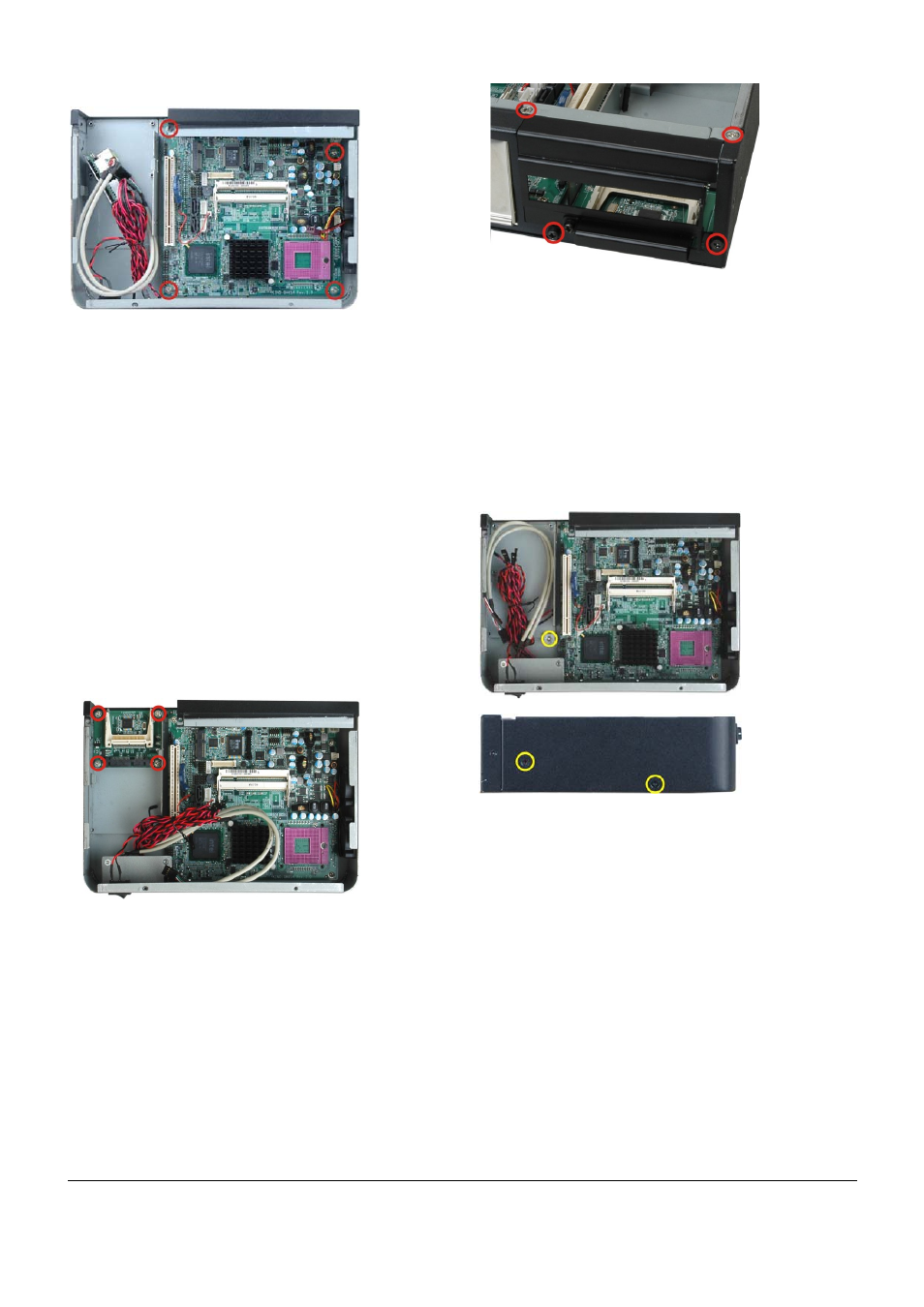
Figure 7: CF Module Installation
Step 4:
Reinstall the expansion slot bracket.
Step 0:
Figure 8: CF Module Installation
STEP 5: DISK DRIVE INSTALLATION
The EBC-3200 chassis has the capacity for one or two 2.5”
internal HDD. To install the HDD, please follow the steps
below.
Step 1:
Remove the HDD bracket from the chassis by
removing three retention screws, two on the left
panel and one inside the chassis.
Inside
Left Panel
Figure 9: HDD Installation
Step 2:
Mount a 2.5” HDD onto the HDD bracket. To do
this, align the four retention screw holes in the
sides of 2.5” HDD with the retention screw
holes in the HDD bracket.
Step 3:
Insert the four retention screws to secure the
HDD with the bracket.
Figure 6: Motherboard Retention Screws