2 jumper settings, 1 at/atx power select jumper settings, Umper – IEI Integration uIBX-200-VX800 v1.04 User Manual
Page 26: Ettings, Table 4-1: jumpers
uIBX-200-VX800 Embedded System
Page 16
4.2 Jumper Settings
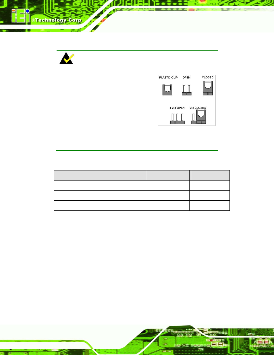
NOTE:
A jumper is a metal bridge used to close
an electrical circuit. It consists of two or
three metal pins and a small metal clip
(often protected by a plastic cover) that
slides over the pins to connect them. To
CLOSE/SHORT a jumper means
connecting the pins of the jumper with
the plastic clip and to OPEN a jumper means removing the plastic clip
from a jumper.
The hardware jumpers must be set before installation. Jumpers are shown in Table 4-1.
Description
Label
Type
AT/ATX power select
JP3
2-pin header
CompactFlash® Master/Slave
CF_MS_SEL1
3-pin header
Clear CMOS
J_CMOS
3-pin header
Table 4-1: Jumpers
The JP3 and J_CMOS jumpers are located on the front side of the motherboard. To
access these jumpers, please remove the bottom panel and motherboard.
4.2.1 AT/ATX Power Select Jumper Settings
Jumper Label:
JP3
Jumper Type:
2-pin header
Jumper Settings:
The AT Power Select jumper specifies the systems power mode as AT or ATX.