2 etx interface connectors, 1 etx-x1 connector, 2 etx i – IEI Integration IEM-LX v1.00 User Manual
Page 42: Nterface, Onnectors, Figure 4-3: etx-x1 connector pinouts, Iem-lx-800 etx cpu module, Page 42
IEM-LX-800 ETX CPU Module
4.2 ETX Interface Connectors
The IEM-LX embedded module has standard four standard ETX interface connectors on
the reverse side of the board. The location of the pins and the pinout descriptions are
given below.
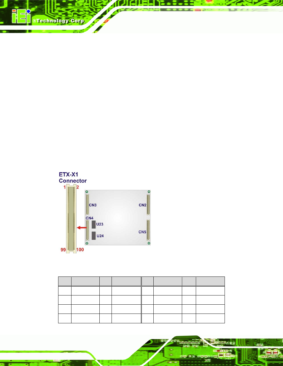
4.2.1 ETX-X1 Connector
CN Label:
CN4
CN Type:
100-pin ETX connector
CN Location:
CN Pinouts:
The standard ETX-X1 connector locations and pinouts are shown below.
Figure 4-3: ETX-X1 Connector Pinouts
Pin
Description Pin
Description
Pin
Description Pin
Description
1 GND
2 GND
51
VCC5 52
VCC5
3 PCICLK3 4 PCICLK4 53
PAR 54
SERR#
5 GND
6 GND
55
PERR# 56
RESERVED
7 PCICLK1 8 PCICLK2 57
PME# 58
USB2#
Page 42
See also other documents in the category IEI Integration Hardware:
- SPCIE-5100DX (180 pages)
- SPCIE-C2060 v1.01 (200 pages)
- SPCIE-C2060 v2.12 (212 pages)
- SPCIE-C2160 (204 pages)
- SPCIE-C2260-i2 (217 pages)
- ROCKY-3786 v4.0 (175 pages)
- ROCKY-3786 v4.10 (147 pages)
- PCIE-Q350 v1.00 (272 pages)
- PCIE-Q350 v1.12 (250 pages)
- PCIE-Q350 v1.20 (250 pages)
- PCIE-Q350 v1.30 (213 pages)
- PCIE-Q57A (159 pages)
- PCIE-G41A2 (151 pages)
- PCIE-Q670 v1.03 (206 pages)
- PCIE-Q670 v2.00 (205 pages)
- PCIE-H610 (181 pages)
- PCIE-Q870-i2 (217 pages)
- IOWA-LX-600 (159 pages)
- PCISA-945GSE v1.01 (207 pages)
- PCISA-945GSE v1.10 (190 pages)
- PCISA-9652 v1.00 (232 pages)
- PCISA-9652 v1.01 (232 pages)
- PCISA-PV-D4251_N4551_D5251 (145 pages)
- PICOe-945GSE (197 pages)
- PICOe-GM45A (198 pages)
- PICOe-PV-D4251_N4551_D5251 v1.00 (154 pages)
- PICOe-PV-D4251_N4551_D5251 v1.10 (154 pages)
- PICOe-PV-D4251_N4551_D5251 v1.11 (155 pages)
- PICOe-B650 (156 pages)
- PICOe-HM650 (174 pages)
- HYPER-KBN (139 pages)
- SPXE-14S (3 pages)
- SPXE-9S v1.00 (5 pages)
- SPXE-9S v1.1 (6 pages)
- SPE-9S v1.00 (4 pages)
- SPE-9S v1.1 (5 pages)
- SPE-6S (3 pages)
- SPE-4S (4 pages)
- PE-6SD3 (4 pages)
- PE-6SD2 v4.0 (4 pages)
- PE-6SD2 v2.10 (3 pages)
- PE-6SD (3 pages)
- PE-6S3 v1.0 (2 pages)
- PE-6S3 v4.0 (4 pages)
- PE-6S2 (4 pages)