Setup guide — sw2 vga da2 af r, Caution, Step 4 — video outputs – Extron Electronics SW2 VGA DA2 AF R Setup Guide User Manual
Page 2: Step 5 — audio output, Step 6 — autoswitching/contact closure, Step 7 — operation, Balanced audio output, Unbalanced audio output
Setup Guide — SW2 VGA DA2 AF R
Step 4 — Video outputs
Connect an RGBHV, RGBS, RGsB, or RsGsBs video display to the 15-pin HD connector
(output B). A 15-pin HD connector (output A) is also provided for a local monitor.
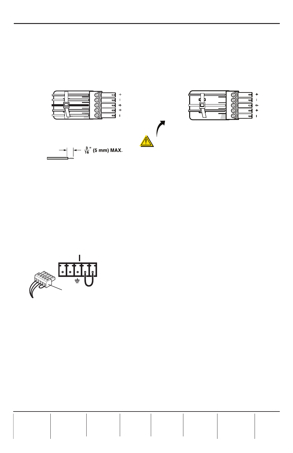
Step 5 — Audio output
Connect an audio device to the 3.5 mm, 5-pole captive screw connector for balanced or
unbalanced audio output. For correct wiring, follow the diagram below.
Do not tin the wires!
Balanced Audio Output
CAUTION
For unbalanced audio, connect the
sleeve(s) to the ground contact.
DO NOT
connect the sleeve(s) to the
negative (-) contacts.
Tip
NO Ground Here
Sleeve(s)
NO Ground Here
Tip
L
R
Unbalanced Audio Output
Tip
Ring
Tip
Ring
L
R
Sleeve(s)
Step 6 — Autoswitching/contact closure
Connect a contact closure control device to the left three pins of the 3.5 mm, 5-pole captive
screw connector.
• Pin 1 —
selects input 1 when connected to ground (pin 3).
• Pin 2 —
selects input 2 when connected to ground (pin 3).
• Pin 3 —
connects to the ground wire (equipment ground).
• Pins 4 and 5 —
if jumpered or shorted together will turn the autoswitching mode on. When
the autoswitching mode is on, the switcher automatically switches to the highest numbered
input that has an active sync signal.
Contact Closure Control
Jumper pins 4 & 5 for
autoswitching.
1 2
CONTACT AUTO-SW
See “Rear Panel Features” in the SW2 VGA DA2 AF R User’s Manual for details.
Step 7 — Operation
Power up all input and output devices and the switcher.
•
If the switcher is in manual switching mode, select an input from the front panel buttons or
by using the contact closure controller.
•
If the switcher is in autoswitching mode (rear panel Contact/Auto-sw pins are jumpered
together), the switcher automatically selects the highest numbered input with an active sync
signal.
•
The image should now appear on screen, and sound from the audio source should be
audible.
If image or audio problems occur, see “Troubleshooting” in the SW2 VGA DA2 AF R User’s
Manual
for further details.
68-460-52
Rev. A
07 09