7 sic-30a-p electrical circuit diagram, 18 10. electrical circuit – Yuh Dak SIC-A series User Manual
Page 58
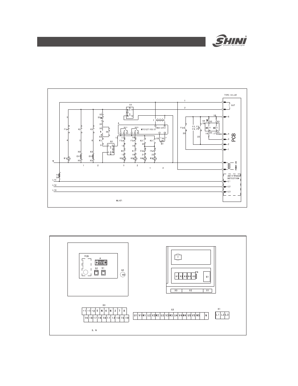
10.7 SIC-30A-P Electrical circuit diagram
10.7.1 Control circuit principle diagram
10.7.2 Components layout diagram
The thermal protector of
compressor
Stand for the power for the protector of the compressor
10-18
10. Electrical Circuit
Pump switch
Pump
motor
contactor
Compressor
Crankcase
heating zone
Compressor
switch
Obligate to connect the optional constant close point of the
protector. When not need to connect the protector, it can
connect short.
Compressor
Compressor
contactor
Compressor
Contactor
Crankcase
heating zone
Fan motor
contactor
Fan motor
contactor