Assembly, Chapter 1 mxt 300 assembly – White’s Electronics MXT 300 User Manual
Page 2
2
Assembly
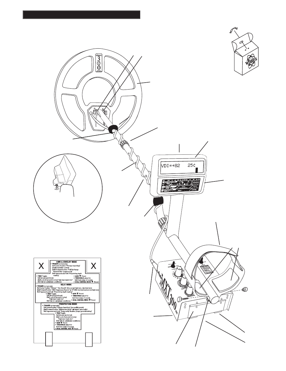
Chapter 1 MXT 300 Assembly
ELBOW
CUP
STRAP
ELBOW CUP
FOAM PADS
INSIDE ELBOW
CUP
CONTROL BOX
“S” ROD
LOOP CABLE
CAMLOCK
WASHERS
BETWEEN
EACH LOOP
EAR & CLEVIS
DISPLAY
TRIGGER
(behind display)
BATTERY
COMPARTMENT
DOOR
BATTERY
COMPARTMENT
LATCHES
LOOP
CONNECTOR
HEADPHONE
JACK
CLEVIS
LOWER
ROD
BOTTOM OF
CONTROL BOX
Twist and insert each end of
handle (provided) through
top of shipping carton into
second fl ap.
(CARRY CARTON)
CABLE RETAINER
CABLE RETAINER
LOOP OR SEARCH
COIL
Remove decal paper from the two rub-
ber bumpers. Install on the bottom of the
control box, one in each of the front corners
(shown below by "X"). Press in place and
hold fi rmly for a few seconds then release.
CABLE
RETAINER
1/ VDI Numbers
2/ Target Identifi cation
3/ Iron Probability
4/ Target Signal Strength
5/ Target Depth
6/ Pinpoint Location
7/ Battery Voltage
Target VDI
reference chart for
all three modes:
/Coin & Jewelry
/Relic
/Prospecting
/Coin & Jewelry
Trigger behind display has multi-
Trigger behind display has multi-
function capability depending
function capability depending
on which of the three
modes you select