Connection, Dimensions – Warner Electric CBC-150 User Manual
Page 2
Warner Electric • 800-234-3369
P-239-21 • 819-0477
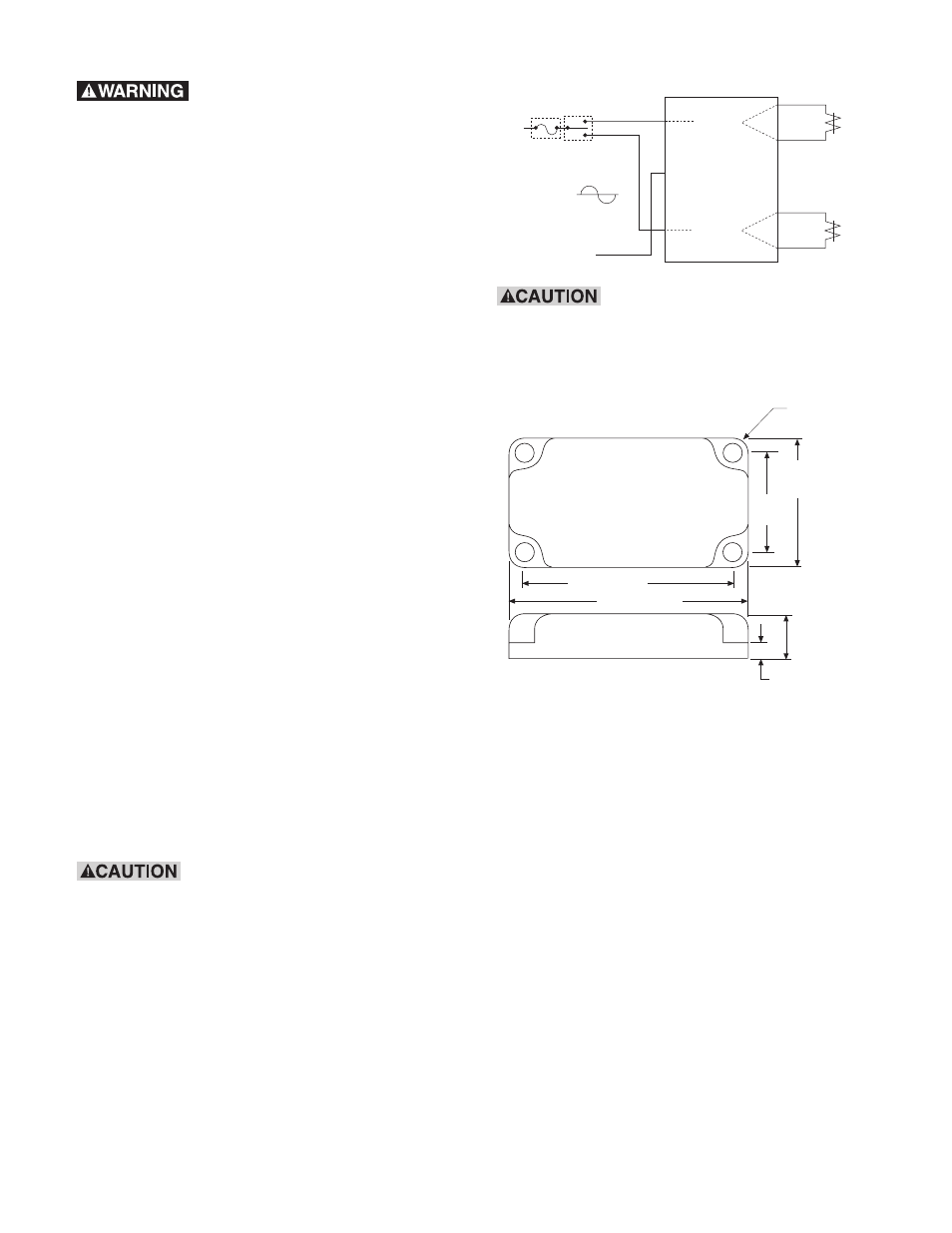
Connection
90 VDC
Clutch or
Brake
Red
Red/White
Blue/White
Blue
(+)
CBC-150
Black/Red
Black/Blue
White
Switch
User Furnished
Fuse
CBC-150-1:
120 VAC
CBC-150-2:
220/240 VAC
HOT
NEUTRAL
BRAKE
RED LED
CLUTCH
GREEN LED
(+)
(-)
(-)
1.8”
(45.7)
2.2”
(55.9)
0.22” (5.59)
4 holes
2.88” (73.2)
3.3” (83.8)
0.56”
(14.2)
0.15”
(3.81)
(All dimensions nominal)
Dimensions
To avoid injury (or even death),
always make certain all power is off before
attempting to install this control or any
electrical equipment.
Please refer to the Connection diagram when
following these instructions.
1. Clutch/Brake Wiring
a. BRAKE (RED LED):
Connect the red wire to one of the
brake leads; connect the red/white
stripe wire to the other lead wire of the
brake (or clutch).
b. CLUTCH (GREEN LED):
Connect the blue wire to one of the
clutch leads; connect the blue/white
stripe wire to the other lead wire of the
clutch (or brake).
2. AC Input Wiring
a. BRAKE (RED LED):
Connect the black/red stripe wire to
the hot side of the AC power source
through the switch and fuse as
indicated.
b. CLUTCH (GREEN LED):
Connect the black/blue stripe wire to
the hot side of the AC power source
through the switch and fuse as
indicated.
c. Connect the white wire to the neutral
side (other hot side for the CBC-150-2)
of the AC power.
3. Secure the control to the conduit box with
the (4) 10-32 Type F screws furnished.
This is a floating type power
supply and is not referenced to AC ground.
Under no circumstances should any of the
output wire leads be connected to earth or
chassis ground as the unit will be destroyed.
Do not commonize any ouput
wiring.