Mounting, Air intake connection – WARN POWERPLANT 9.5 User Manual
Page 7
WARN INDUSTRIES
9 73203B0
MOUNTING
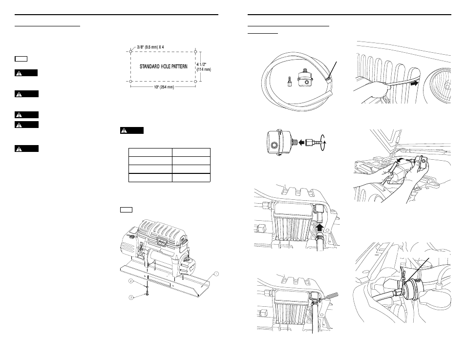
Mounting Bolt Pattern:
Standard: 10” x 4.5”, 254 mm x 114.3 mm
Choose a mounting location that is sufficiently
strong enough to withstand the maximum pulling
capacity of your winch.
WARNING
Always confi rm required bolt length to
ensure proper thread engagement.
Step 1 - Mount the Winch
Winch mounting kits are available from your
WARN Dealer to satisfy nearly all applications. For
information on available kits, contact your WARN
product dealer.
NOTICE For optimal performance and the results you expect,
WARN mounting plates are strongly recommended.
CAUTION
To prevent accidental activation of the winch
and serious injury, complete the winch installation and attach
the hook before installing the wiring.
WARNING
Always choose a mounting location that is
suffi
ciently strong enough to withstand the maximum pulling
capacity of your winch.
WARNING
Never use bolts that are too long.
WARNING
Always spool the winch rope onto the drum
in the direction specifi ed by the drum rotation labels on the
winch and/or in the documentation. This is required for the
automatic brake (if so equipped) to function properly.
WARNING
Always wind the winch rope on the bottom
(mount side) of the drum.
Only the mounting orientations shown are
possible for safe winching operation (Refer to
the following diagrams for proper mounting
orientation). All others are improper and
inappropriate. The mounting details indicate the
proper torque levels.
The use of recommended bolt and lock washer
combinations torqued to recommended levels will
prevent vibration during operation. Specifications
listed below. Mounting system will dictate bolt
length.
Mounting Details:
(1) Smooth and fl at, thickness = 1/4” (6.4 mm)
(2) 3/8” (9.525 mm) lockwasher X 4
(3) 3/8-16 X 1 1/4” long, grade 5 bolt X 4
Torque 30-35 ft. lbs. (41-47Nm)
Mounting Orientation:
NOTICE This winch is designed for feet down mounting only.
Plate Thickness
Bolt Length
1/4” (7 mm)
1.25” (32 mm)
3/8” (10 mm)
1.5” (40 mm)
1/2” (13 mm)
1.5” (40 mm)
WARN INDUSTRIES
73203B0 10
AIR INTAKE CONNECTION
Step 2 - Air Intake Hose & Filter
Installation
1. Locate air intake kit contents. Place the small
hose clamp onto end of the intake hose.
2. Connect the barb fitting to the airtake filter.
3. From the back side of the winch, locate the
hose fitting on the compressor head and push
the hose on.
4. Tighten clamp securely.
5. Route the air intake hose thru the vehicle
grille or bumper openings into the engine
compartment.
6. Install the filter onto the end of the hose.
7. Mount filter up as high as possible. Use the
supplied tie wraps or other means to secure the
hose and filter.
Tighten tie wrap securely
hose clamp