Taco antenna, Muldipol military antenna specifications, Vhf frequencies only – Wade Antenna D2000 Series User Manual
Page 2: Operation environmental, Electrical
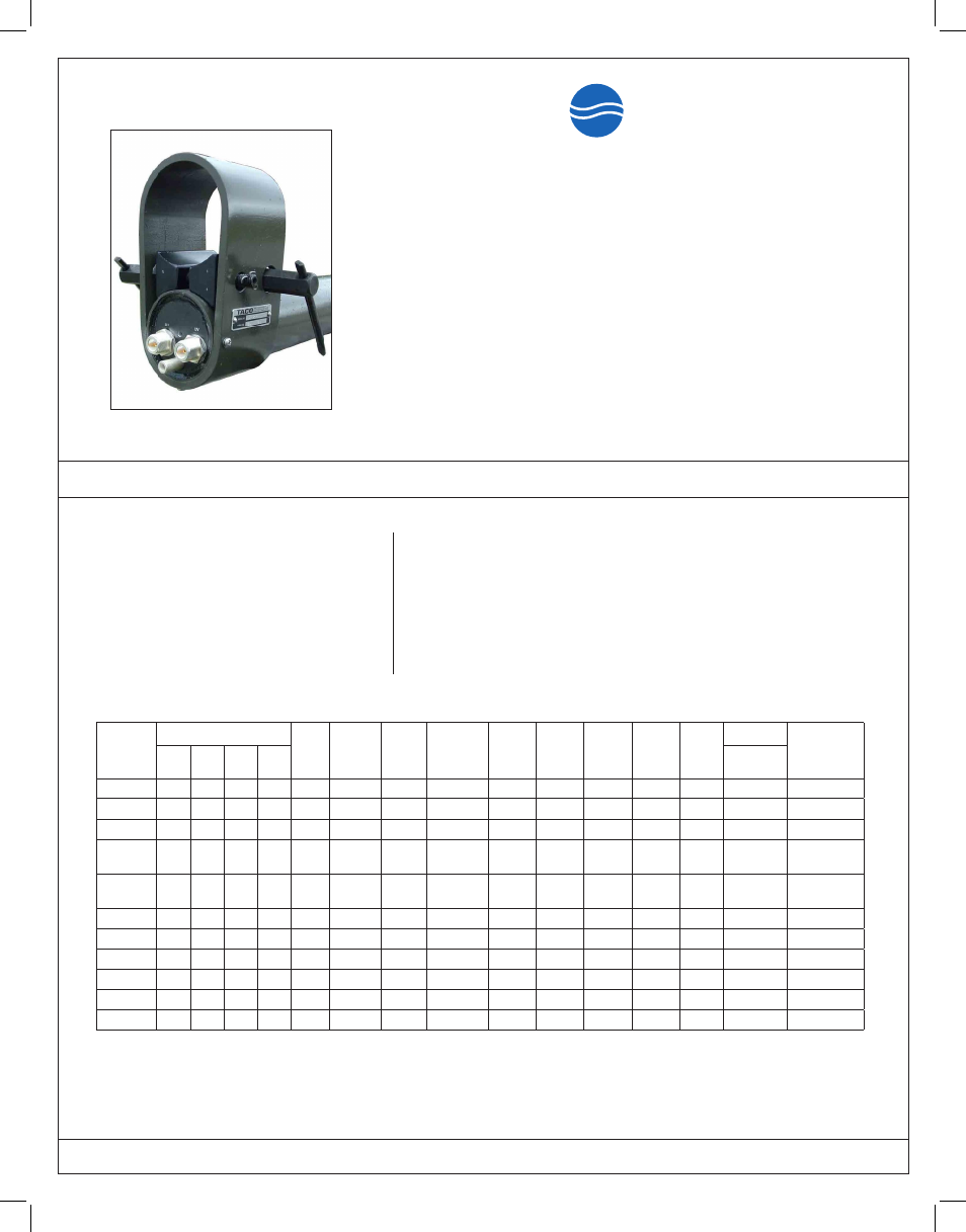
VHF FREQUENCIES ONLY
MODEL
VHF FREQUENCY (MHz)
GAIN
(dBi)
# OF
OUTPUTS
HPBW
DEGREE
MOUNTING
DIAMETER
LENGTH
INCHES
LENGTH
CM
WEIGHT
LBS
WEIGHT
KG
COLOR WIND LOAD
NSN
108-
174
116-
150
118-
136
150-
174
0.5” RADIAL
ICE
D2212
XX
2.0
2
75
1
152.5
386.7
12.5
5.7
Green
2.0
5985-01-315-7443
D2212A
XX
2.0
2
75
1
121.38
386.7
12.5
5.7
Green
2.0
-
D2216
X
2.0
1
75
2
54.5
138.4
5.5
2.5
Green
0.7
5985-01-050-7522
D2260
XXX
2.0
3
75
1
196.5
499.1
25.0
11.3
2 Piece
Green
2.6
5985-01-438-1459
D2260A
XXX
2.0
3
75
1
193.5
491.5
25.0
11.3
2 Piece
Green
2.5
-
D2261A
XX
4.5
1
40
1
140.5
356.9
19.0
8.6
Green
1.7
-
D2261A1*
XX
4.5
1
40
3
140.5
356.9
19.0
8.6
White
2.1
5985-01-050-7525
D2268
XXX
5.5
1
25
1
200.0
508.0
23.3
10.6
Green
3.0
-
D2272*
XX
2.0
2
75
3
152.5
386.7
17.5
8.0
White
2.3
5985-01-053-5108
D2272A
XX
2.0
2
75
2
152.5
386.7
17.0
7.7
Green
2.3
-
D2276*
X
2.0
1
75
3
54.5
138.4
5.5
2.5
White
0.7
5985-01-050-7522
Muldipol Military Antenna Specifications
www.tacoantenna.com
TACO Antenna
A d i v i s i o n o f W A D E A n t e n n a , I n c .
X – Denotes number of active elements
* COTS Product
The process employed in the TACO antennas incorporates the patented
MULDIPOL™ concept. The utilization of this technique results in a unit which
has excellent “broadband” halfwave dipole characteristics over the entire
operating frequencies.
The desired “figure eight” radiation pattern is generally constant throughout
the band. Through “broadband” suppression of extraneous currents upon the
transmission line, the undesirable “Clover Leaf” pattern is avoided.
By design, the outer conductors of both halves of each dipole are at the same
DC ground potential. A ground is provided at the base of each antenna for
supplemental grounding capability.
OPERATION
ENVIRONMENTAL
• Built to Military standards
• Rain, salt-fog, sand, dust and fungus to
MIL-STD 810F
• Temperature, barometric pressure and
humidity to MIL-STD 210C
ELECTRICAL
• Isolation (min.) 30.0 dB
• Polarization Vertical
• Omni Directional +0dB/-1dB
• Uniformity (azimuth)
• VSWR (max.) 2:1
(except D2211, 2.3:1)
• Terminals “N” Female
• Terminal Impedance 50 Ohms
• VHF Applied Power 350 W
• UHF Applied Power 250W
• Vertical Beam Deviation ±10° (horizon)
• Operating Temp -40
o
to 70
o
C
(-40
o
to 158
o
F)
MOUNTING DIAMETER KEY
(1) = 3 inch Mast Size O.D. Also available for 2.875 upon request
(2) = 1.5 to 3 inch Mast Size O.D.
(3) = 2.875 inch Mast Size O.D. / 1.66 inch adapter also included