Wade Antenna WL6-FM_S User Manual
Antenna, inc, Wade, Single low band antenna models
WADE Antenna Inc.
29 Sharp Road
Brantford, Ontario, N3T 5L8 Canada
Tel: 519.756.7157
Fax: 519.756.5056
WADE
Antenna, Inc.
(800) 463-1607
www.wadeantenna.com
There are four rugged low band models, each engineered
to provide optimum performance over the desired band.
Pure log periodic design and cantilever mount ensure
superior electrical performance and pattern predictability
for maximum rejection of interfering signals. A newly
designed feed point accepts a standard 75 Ohm CATV
housing connector. The use of corrosion resistant materials
combines long life with trouble-free, reliable performance.
SINGLE LOW BAND ANTENNA
MODELS:
• WL 2-4/S
• WL 3-5/S
SPECIFICATIONS:
ElEctrical
Specification
WL 2-4/S
WL 3-5/S
WL 4-6/S
WL 6-FM/S
FREQUENCY RANGE
54-72 MHz
60-82 MHz
66-88 MHz
82-108 MHz
CHANNELS
2,3&4
3,4&5
4,5&6
6&FM
GAIN
9 dBi
9 dBi
9 dBi
9 dBi
IMPEDANCE
75 Ohm
75 Ohm
75 Ohm
75 Ohm
VSWR
<1.25:1
<1.25:1
<1.25:1
<1.25:1
FR:BK RATIO
>25 dB
>25 dB
>25 dB
>25 dB
POLARIZATION
H or V
H or V
H or V
H or V
H. BEAM WIDTH
60 deg.
60 deg.
60 deg.
60 deg.
V. BEAM WIDTH
90 deg.
90 deg.
90 deg.
90 deg.
SIDE LOBE SUPPRESSION
>30 dB
>30 dB
>30 dB
>30 dB
CONNECTORS**
“F” Connector
STD. MOUNT
1/2" U-Bolts to Fit 3" O.D. Pipe
*Where interfering signals such as co-channel, adjacent channel and ghosting are present, custom arrays can be designed to reduce the level of
interference by as much as 40 db in most cases.
LOW BAND ANTENNA
A qualified structural engineer should be consulted prior to mounting an antenna on a tower or a support structure.
• WL 4-6/S
• WL 6-FM/S
Printed in Canada 2005
W
ADE
A
NTENNA
L
TD
.
1-800-463-1607
www.wade-antenna.com
WADE ANTENNA
SINGLE LOW BAND ANTENNA
MODELS:
ࡗWL 2-4/S
ࡗWL 3-5/S
ࡗWL 4-6/S
ࡗWL 6-FM/S
LOW BAND ANTENNA
There are four rugged low band models, each
engineered to provide optimum performance over
the desired band. Pure log periodic design and
cantilever mount ensure superior electrical per-
formance and pattern predictability for maximum
rejection of interfering signals. A newly designed
feed point accepts a standard 75 Ohm CATV
housing connector. The use of corrosion resistant
materials combines long life with trouble-free,
reliable performance.
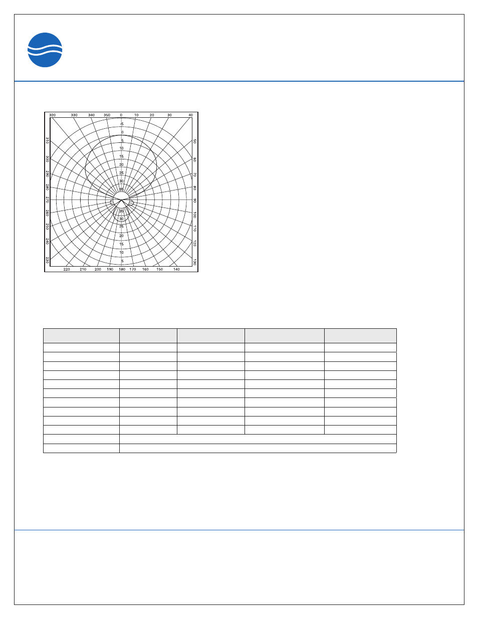
WADE LOG PERIODIC ANTENNA
SINGLE ANTENNA
ELECTRICAL SPECIFICATIONS
SPECIFICATION
WL 2-4/S
WL 3-5/S
WL 4-6/S
WL 6-FM/S
FREQUENCY RANGE
54-72 MHz
60-82 MHz
66-88 MHz
82-108 MHz
CHANNELS
2,3&4
3,4&5
4,5&6
6&FM
GAIN
9 dBi
9 dBi
9 dBi
9 dBi
IMPEDANCE
75 Ohm
75 Ohm
75 Ohm
75 Ohm
VSWR
<1.25:1
<1.25:1
<1.25:1
<1.25:1
FR:BK RATIO
>25 dB
>25 dB
>25 dB
>25 dB
POLARIZATION
H or V
H or V
H or V
H or V
H. BEAM WIDTH
60 deg.
60 deg.
60 deg.
60 deg.
V. BEAM WIDTH
90 deg.
90 deg.
90 deg.
90 deg.
SIDE LOBE SUPPRESSION
*
>30 dB
>30 dB
>30 dB
>30 dB
CONNECTORS
**
“F” Connector
STD. MOUNT
1/2" U-Bolts to Fit 3.5" O.D. Pipe
*
WHERE INTERFERING SIGNALS SUCH AS CO-CHANNEL, ADJACENT CHANNEL AND GHOSTING ARE PRESENT,
CUSTOM ARRAYS CAN BE DESIGNED TO REDUCE THE LEVEL OF INTERFERENCE BY AS MUCH AS 40 dB IN MOST
CASES.
A-1