Hdsl2 troubleshooting guide, Hdsl2 deployment guidelines, Turn up guidelines – ADTRAN 3192 H2TU-C User Manual
Page 2: Troubleshooting guidelines
PRICING AND AVAILABILITY 800.827.0807
TECHNICAL SUPPORT 800.726.8663
RETURN FOR REPAIR 256.963.8722
www.adtran.com
61221001L6-30B
HDSL2 TROUBLESHOOTING GUIDE
HDSL2 DEPLOYMENT GUIDELINES
■
Cable pairs must be non-loaded
■
Total bridged tap length < 2.5 kft
■
No single bridged tap >2 kft
■
196 kHz insertion loss < 35 dB
■
Pulse attenuation (ATTEN on HDSL2 Span Status Screen) < 30 dB
■
Maximum loop resistance is 900
Ω
■
Impulse noise < 50 dBrn as measured using a 50 kb filter
■
Wideband noise
≤ 31 dBrn as measured using a 50 kb filter
TURN UP GUIDELINES
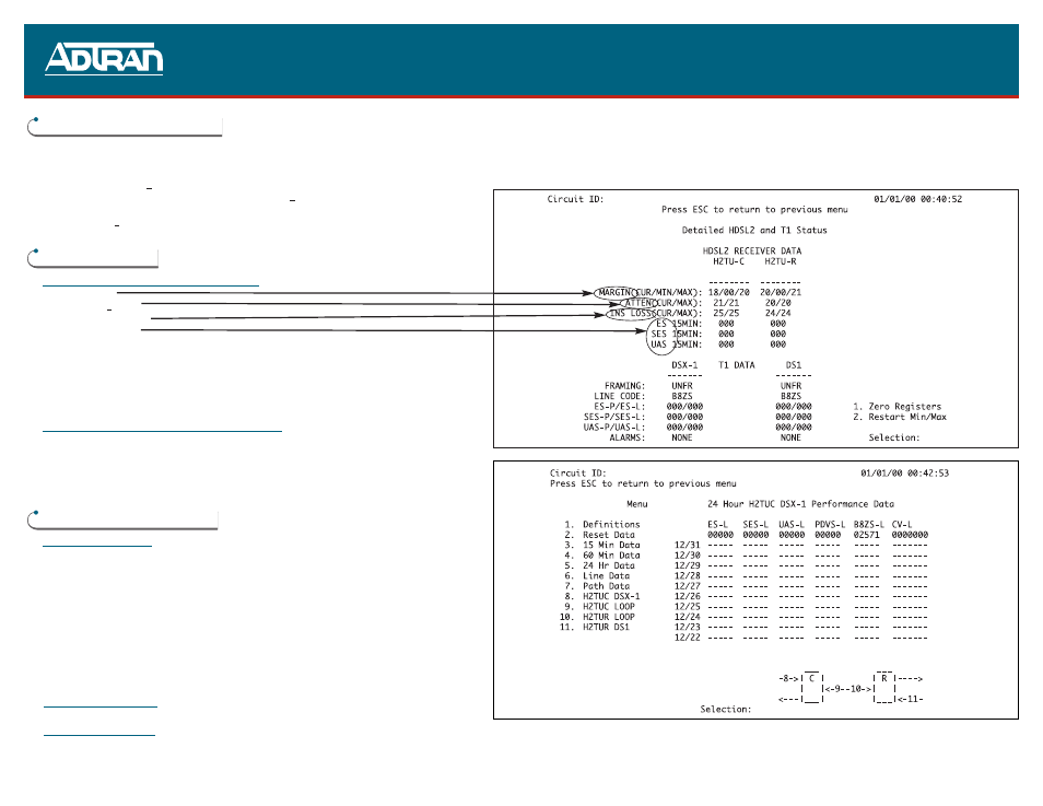
Circuit Parameters Under Normal Operation
■
Margin
≥ 6 dB
■
Attenuation < 30 dB
■
Insertion Loss
≤ 35 dB
■
No ES, SES, or UAS
If these parameters are met, then the circuit will provide quality service. If not, a cable problem or
excessive loss situation is probable. In this case, a more detailed cable analysis is required to insure that
all HDSL2 Loop Specifications are met.
These conditions may also be the result of intermittent cable faults or intermittent noise impairments. If
intermittent problems are suspected, utilize the Performance History Screen (Main Menu selection #5) to
assist in troubleshooting. An example of a Performance History Screen is illustrated in the bottom right-
hand corner.
Front Panel Indications Under Normal Operation
■
STATUS LED will be Green (solid)
NOTE: The circuit must have DSX-1 signal (from Network) and DS1 signal (from Customer) in order for
the LED to be Green. If either DSX-1 or DS1 signal is not present, the LED will be Red.
■
The four-character display will flash the current loop margin for the HDSL2 loop. No alarm or error mes-
sages will be displayed. After five minutes of no activity, the display will turn completely Off. It will
remain Off until MODE or SELECT is activated or a message other than loop margin is to be displayed.
TROUBLESHOOTING GUIDELINES
Front Panel Indicators
■
All indicators are Off.
1. Verify that -48 Vdc is properly connected.
2. Inspect fuse and verify that it is not blown.
3. Insert the H2TU-C into a slot known to be good and verify that the
STATUS indicator is lit. If card fails replace H2TU-C.
■
Status LED is Blinking Red
Poor signal quality or loss of sync. Use basic troubleshooting procedures to
identify cable pair problems.
■
Status LED is Solid Red
If customer equipment is not installed, initiate an H2TU-R to Network
Loopback and perform BERT test. If this test fails, or the craft interface
indicates a loss of sync, then there is a problem with the cable pair that
should be resolved through normal troubleshooting procedures.
■
Status LED is Blinking Green Errors are being taken on the DSX, DS1, or HDSL2 loop. The craft interface
screens will identify the source. BERT test to the appropriate loopbacks
should isolate the problem.
Four Character Display
■
The error messages for this display are defined on page 1 of this guide.
Craft Interface Screens
■
Detailed Status Screen
Provides instant view of system status (Main Menu selection “3”, Span Status selection “2”)
■
Alarm History Screen
Provides a record of system alarms (Main Menu selection “8”)
■
Event History Screen
Provides last 100 events on the system (Main Menu selection “9”)
■
Performance History Screens Provide performance data for all points in the system (Main Menu selection “5”)
■
For complete Installation and Maintenance: (877) 457-5007, Document #529,
#555, and #556. Please have your fax number available.
■