Vanguard RFD-200 S3 User Manual
Page 10
RFD-200 S3 USER’S MANUAL
REV 1
7
2.0 FUNCTIONAL
DESCRIPTION
2.1
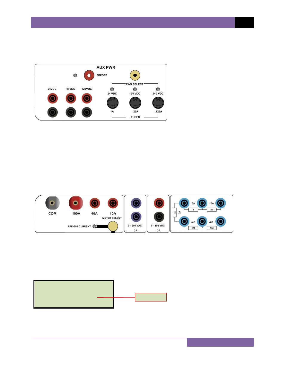
RFD-200 S3 Auxiliary Power Supply
The RFD-200 S3 provides 3 auxiliary power supplies (24 Vdc, 48 Vdc, and 125 Vdc) for powering
electronic relays. Each power supply is fuse-protected. The power supply outputs are controlled
by the auxiliary power supply
[ON/OFF]
button. The LED next to the
[ON/OFF]
button is
illuminated when the power supply output is turned on.
Only one auxiliary power supply can be selected at a time. The
[PWS SELECT]
button (item
21 in Figure 1) is used to select the power supply. The active power supply is indicated by an
illuminated LED above the corresponding voltage label.
2.2
RFD-200 S3 Current and Voltage Sources
The RFD-200 S3 front panel offers three AC current source terminals (100A, 40A, 10A). Only one
current source should be used at a time. The
[METER SELECT]
button is used to select
whether to display the current generated by the RFD-200 S3 or the current input at the
[EXT
INPUT CURRENT]
terminals. The
[RFD-200 CURRENT]
LED will be illuminated when an
internal RFD-200 current source is in use and the output current is displayed on the LCD. The
internal current is labeled as “Int I:” on the LCD screen as shown below:
Two isolated voltage sources are also available, one 0-250 Vac and one 0-300 Vdc. Both the
current and voltage sources are controlled by the
[OUTPUT CONTROL]
knob .
0mS 0.0CY
V Mtr: -0.003 V
Int I: 0.080 A
Ext I: -0.001A
Internal Current