TREND INC2 User Manual
Page 2
2
INC2 Installation Instructions TG200231Issue 1/E 09/11/06
INC2
Installation Instructions
3.1
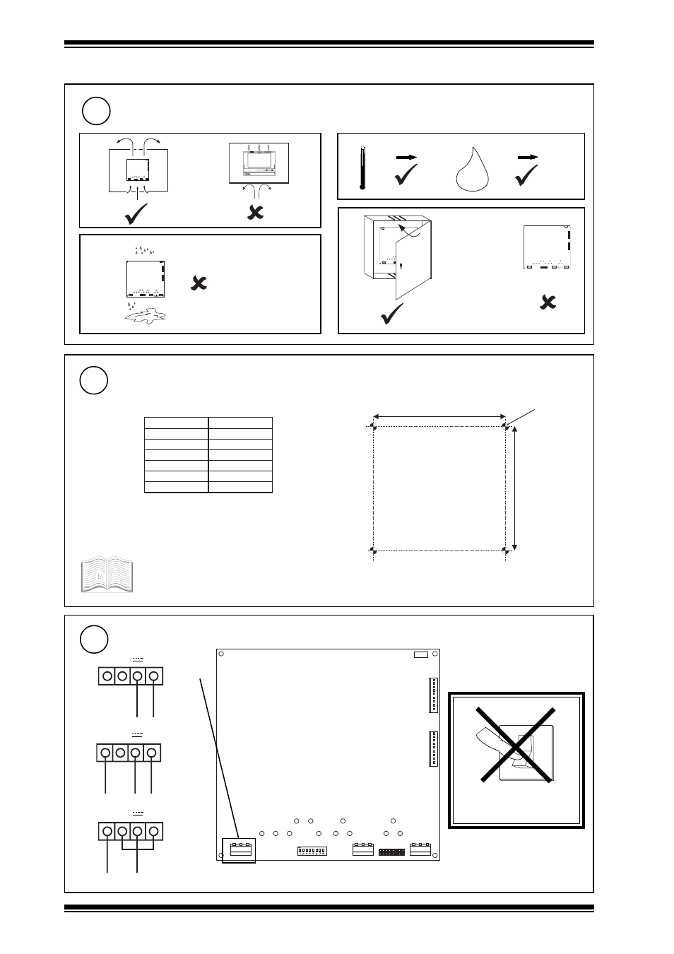
Installation - Mounting
(Continued)
Mount the Node
2
The INC2 can be fitted into enclosures and controllers as shown in the table below:
* INC2 board fits with 3 screws in normal node position or
fits in NDP position (if no NDP). Must use NDP position
if RDS fitted.
See appropriate enclosure/controller
installation instructions for more details about
node installation.
151 mm (5.94")
141 mm (5.55")
4 off 4 mm
J 7
E T 1
J 1 6
D e v B
J 1 5
D e v A
J 9
J 8
L a n B
L a n A
J 7
E T 1
J 1 6
D e v B
J 1 5
D e v A
J 7
E T 1
J 1 6
D e v B
J 1 5
D e v A
J 9
J 8
L a n B
L a n A
J 7
E T 1
J 1 6
D e v B
J 1 5
D e v A
J 9
J 8
L a n B
L a n A
a
d
c
H O
2
0 °C
(32 °F)
+45 °C
(113 °F)
0 %RH
95 %RH
b
I N C 2
Requirements
2
INC2/USA: The unit
is UL rated as
'UL916 accessory
to open energy
m a n a g e m e n t
equipment'.
B
B
T
E
N
/
B
T
E
N
9
+
2
0
1
/
+
1
0
1
Q
I
9
+
1
1
1
Q
I
9
+
1
3
1
Q
I
9
x
5
2
Q
I
9
*
2
4
2
/
1
4
2
Q
I
9
3
3
2
/
1
3
2
Q
I
9
Connecting Power
3
J 7
E T 1
J 1 6
D e v B
J 1 5
D e v A
J 9
J 8
L a n B
L a n A
DO NOT APPLY
POWER
0
I
18 Vac
18 Vac
(isolated)
~ ~ 0V
18
18 0
18-0-18 Vac
~ ~ 0V
+24 V
0V
24 Vdc
~ ~ 0V
terminal size 0.5 to 2.5 mm
2
(14 to 20 AWG)
INC2 consumption <=5 VA