Installation instructions - sheet 1 iqlrouter/230, Connect lon, 3 installation - fixing (continued) – TREND IQLROUTER_230 User Manual
Page 3: Polarity independent, Network side a network side b
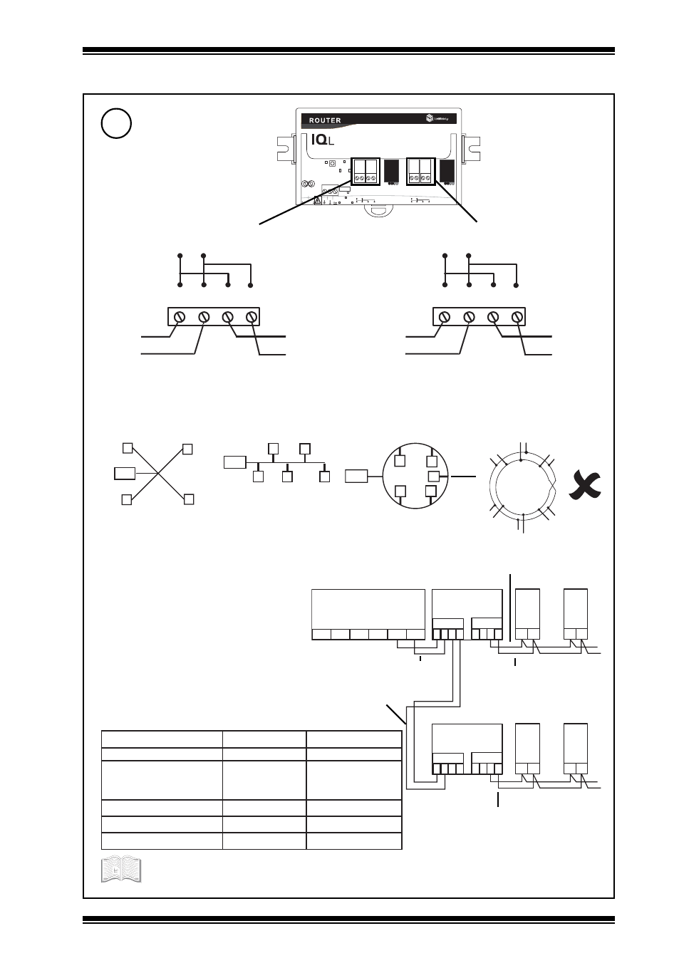
IQLROUTER/230 Installation Instructions TG200792 Issue 1/A 1/7/04
1 - 3
Installation Instructions - Sheet 1
IQLROUTER/230
1.3
INSTALLATION - FIXING (Continued)
O N
O F F
O F F
B U S F R E E
O F F
B U S F R E E
1
2
3
4
5
P K T
2 4 V
6
7
8
9
1 0
1 1
1 2
1 3
L O N - A
L O N - B
A - S V C - B
2 3 0 V A C
5
T e r m i n a t o r
T e r m i n a t o r
T e r m i n a t o r
Lon - FTT (free topology)
Star topology
Bus topology
Loop topology
*Terminate Lon bus at one point only
Polarity independent
Connect Lon
*
*
*
Do not allow wires to cross on a loop
Lon
Lon
4 5 6 7
L o n A
Polarity independent
Lon
Lon
8 9 1 0 1 1
L o n B
Network Side A
Network Side B
LonA
SCN
LonB
LonA
SCN
LonB
LINC
A
1
IQL ROUTER
2 3 4
B
1 2 3 4
IQL
x
y
A
1
IQL ROUTER
2 3 4
B
1 2 3 4
IQL
x
y
IQL
x
y
IQL
x
y
Maximum 64 nodes per
Lon segment
Maximum 40 IQLs (and
LONCs) per virtual Lan
Terminate at IQLROUTER using integrated Lon
terminater link A (see step 6).
Terminal size 0.5 to 2.55 mm
2
(14 to 20 AWG)
e
l
b
a
C
h
t
g
n
e
l
s
u
b
x
a
M
e
d
o
n
o
t
e
d
o
n
x
a
M
2
0
1
5
8
n
e
d
l
e
B
)
s
d
y
5
4
5
(
m
0
0
5
)
s
d
y
5
4
5
(
m
0
0
5
d
n
e
r
T
0
0
2
/
F
H
/
6
1
/
0
/
1
/
P
T
)
1
7
4
8
n
e
d
l
e
B
(
)
s
d
y
5
4
5
(
m
0
0
5
)
s
d
y
0
3
4
(
m
0
0
4
G
W
A
2
2
,
V
I
l
e
v
e
L
L
U
)
s
d
y
5
4
5
(
m
0
0
5
)
s
d
y
0
3
4
(
m
0
0
4
8
.
0
x
2
x
2
Y
)
t
S
(
Y
J
)
s
d
y
5
4
5
(
m
0
0
5
)
s
d
y
0
5
3
(
m
0
2
3
G
W
A
4
2
,
5
.
t
a
C
A
8
6
5
A
I
T
)
s
d
y
0
9
4
(
m
0
5
4
)
s
d
y
0
7
2
(
m
0
5
2
If used with LPT-10 (powered bus), cable lengths differ - see Link Power Transceiver
User’s Guide (078-0105-01C) available from Echelon
Terminated using integrated Lon
terminater link B (see step 6).
Terminated using integrated Lon terminater link
B (see step 6)
Integrated Lon terminater link A set to
OFF (see step 6)