Qphy-displayport software option – Teledyne LeCroy QPHY-DisplayPort User Manual
Page 19
QPHY-DisplayPort Software Option
QPHY-DisplayPort-OM-E Rev A
19
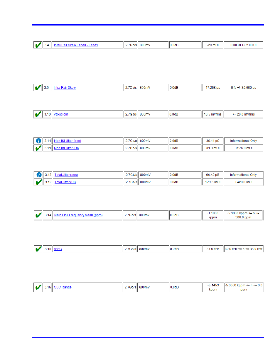
This test measures the skew between two lanes. The value reported is the actual skew measured minus the
nominal skew expected between the two lanes.
3.5 Intra-Pair Skew Test
This test measures the skew between D+ and D- of a single lane. The skew is measured at the 50% level of the
transition, as determined using the voltage level as defined in Test 3.2. Therefore, as with Test 3.2, this
measurement must be made using a PRBS7 pattern as the input signal and cannot be applied to other patterns,
such as the D10.2 pattern.
3.10 AC Common Mode Noise
This test measures the root mean square of the common mode voltage.
3.11 Non-ISI Jitter Measurements
This test measures the non-inter-symbol interference jitter. The result is reported in seconds and in unit intervals.
3.12 Total Jitter Measurements
This test measures the total jitter. The result is reported in seconds and in unit intervals.
3.14 Main Link Frequency Compliance
This test measures the mean operating frequency of the input signal. The result reported is the deviation from the
nominal frequency in parts per million.
3.15 Spread Spectrum Clock Modulation Frequency
This test measures the spread spectrum modulation frequency. This measurement only applies when spread
spectrum is enabled.
3.16 Spread Spectrum Clock Modulation Deviation
This test measures the range of frequency deviation due to spread spectrum. This measurement only applies
when spread spectrum is enabled. The result reported is the maximum deviation minus the minimum deviation
from the nominal frequency in parts per million.
§ § §