Connecting to a can bus circuit – Teledyne LeCroy CANbus TD - Quick Reference Guide User Manual
Page 4
All of the normal connection
rules apply when connecting the
CANbus TD Trigger Module to your
bus. The bus must be terminated
correctly, and CANH, CANL, GND,
etc.must be connected to the
right locations. If you don’t
connect to the bus correctly, the
CANbus TD Trigger Module may
generate error frames, may load
down your signal, and will not
trigger. Use your own cable, or a
LeCroy-supplied cable to connect
to your CAN Bus circuit; and
connect your circuit to the Trigger
Module using the 9-pin connector.
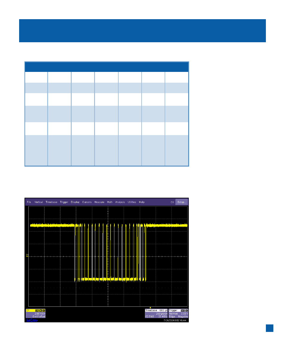
It is usually easiest to view the raw
channel input first before setting
up the CAN Trace with a defined
CAN Source. Reference your
oscilloscope’s on-line Help if you
have questions about displaying
a signal on an oscilloscope channel.
After the setup is verified, it is then
a simple matter to turn the channel
OFF and view the CAN Trace, with
decoding (as desired),and any other
non-CAN signals.
3
Connecting to a CAN Bus Circuit
251
1041 1050 1054 5790c
10011S
2 CANL
CANL
CANL
CANL
CANL
3
GND
VB-
VB-
4
100 Ω
(HS Mode)
7
CANH CANH CANH CANH CAN CANH
Notes Connect
Connect
Connect
120 Ω
120 Ω
120 Ω
between between
between
pins 2 + 7 pins 2 + 7 pins 2 + 7
Pin #
Transceiver/ Trigger Coupler