Connecting to a can bus circuit – Teledyne LeCroy CANbus TD - Quick Reference Guide User Manual
Page 3
2
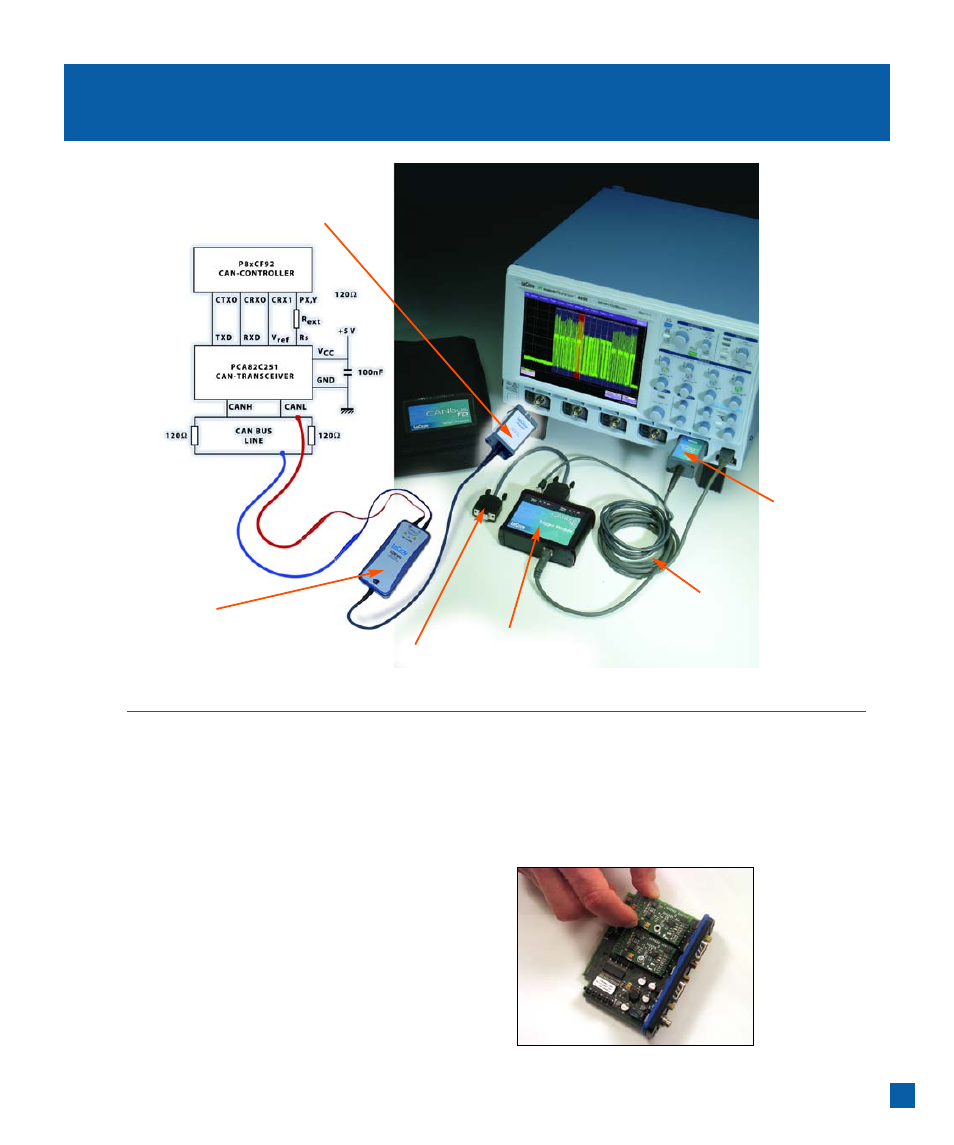
Connecting to a CAN Bus Circuit
The CANbus TD Trigger Module operates as a “node”
on the CAN Bus. It contains a Microcontroller, CAN
controller, and Transceiver (Trigger Coupler) and
interfaces to the CAN circuit just like any other
node on the bus. However, the Trigger Module only
provides triggering capability. In order to “view”
the actual CAN physical signal on the oscilloscope
display, you must also probe the CANH and CANL
lines with the included PP007 single-ended probes,
or a differential probe (such as the LeCroy ADP305
or AP033) and input this probe signal(s) to an
oscilloscope channel.
You will need to match the Trigger Coupler (Transceiver)
in the Trigger Module to the one on your bus. Trigger
Module has a 251 transceiver pre-installed. It is easy
to install a different Trigger Coupler. Reference the
CANbus TD Operator’s Manual for complete instructions.
Use a differential
probe, or two
single-ended probes,
to view the signal
on the oscilloscope
Plug into any channel
To trigger, connect your own 9-pin to 9-pin
cable to your ECU 9-pin connector, or use a
LeCroy supplied adapter cable
Trigger Module
Trigger Couplers are installed
in the Trigger Module
USB 2.0 Cable
Powers the Trigger Module
and downloads trigger setup
from the oscilloscope
Oscilloscope
Interface Module
Connect to Ext, or a channel