Teledyne LeCroy CPCI64 User Manual
Page 6
6
FOR CPCI-64
To increase the +5V current limit you must remove the jumper/resistor at R32 and perform the
following reworks:
• To change the current limit to 8A install a 10k resistor at location R32 and a 6.2k resistor at
location R22. This does not affect the current measurement reading.
• To change the current limit to 10A install a 10k resistor at location R32 and R22. This does not
affect the current measurement reading.
To increase the +3.3V current limit, you must supply +3.3V current from the motherboard or an
external power supply. Perform the following rework:
• To change the current limit to 8A install a 4.7K Resistor on top of R36. This does not affect the
current measure reading.
EXTERNAL POWER SUPPLY
This feature is not supported by PCIAX Rev A. There are no jumpers on the PCIAX Rev A board to
re-configure for the external supply.
An external terminal J5 is used for the external power supply input. However, remember never to connect
any supply to these inputs so long as you have JP4, JP5, JP6 and JP7 installed. If you want to use the
external supply as an input, you must remove these 4 jumpers to avoid any conflict with the bus voltages.
These jumpers are, however, independent from each other. For instance if you would want to bring in only
a +5V from the external supply and continue to use the bus voltages for +12V, -12V, and +3.3V, you
would only need to remove JP5. The list below matches each jumper to its supply:
JP4 = -12V
JP5 = +5V
JP6 = +12V
JP7 = +3.3V
JP7 1-2 for 3.3V from on-board regulator, JP7 2-3 from the bus, not installed from the external supply
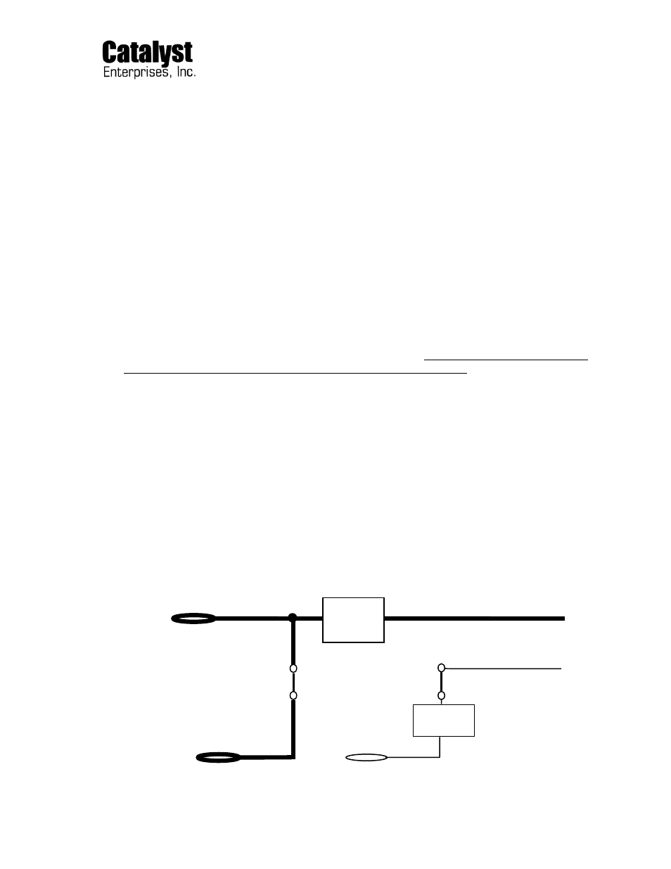
The following diagram indicates the interconnection of the Unit-Under-Test voltages to the bus voltages
and the external voltages:
+5VE
ON-OFF
+5V out to UUT
Circuitry
VIO to UUT
JP5
JP10
ON-OFF
Circuitry
+5V from the bus
+VIO from bus