Teledyne LeCroy PC_AT 200 User Manual
Page 6
4
The list below identifies which jumper is for which supply:
JP1 = +12V
JP2 = -12V
JP3 = -5V
JP4 = +5V
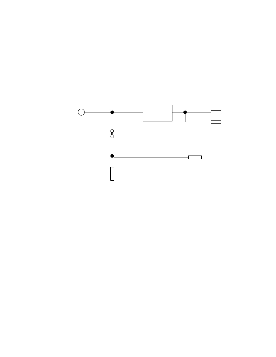
The following diagram indicates the interconnections of the UUT voltages
to the bus voltages and the external voltages.
+5VE
to UUT, +5BV
On-Off
Circuitry
Auxiliary outputs
+5BV
JP4
Auxiliary Outputs, +5V
+5V (from the Bus)
As indicated in the diagram, there will be a conflict if the external
supply is connected while the jumper is still in place. This circuit is
repeated for each of the 4 voltages.
If you are using external power supplies do not forget to connect the
Ground (GND) signals. If your external power supply outputs are not
isolated, make sure the ground of the PC (containing the extender board)
and the ground of the power supply are at the same voltage level with
respect to a common point, before connecting the GND signal.
AUXILIARY OUTPUT VOLTAGES
The voltages at the pads to the left of Q1/Q2/Q3 are auxiliary output
voltages. The voltages with "B" reference designations are switched
voltages. Meaning they will be turned On and Off when the extender power
is turned On and Off. The other voltages are directly from the bus and
will be On as long as the system is On. These voltages are not fused.