Probe adjustment – Teledyne LeCroy PP006A User Manual
Page 2
Probe Adjustment
LF Adjustment
LF compensation is made by connecting the probe to the cal signal and adjusting the
compensation trimmer in the BNC-box at end of the probe. Connect the BNC end of the
probe to a channel of the oscilloscope. Connect the sprung hook end (1) and the ground lead
(2) to the CAL out and GND on the scope Calibrator area. The CAL signal is available in
many speeds. Select the Utilities in the scope to set the CAL to 1 kHz. Turn the scope
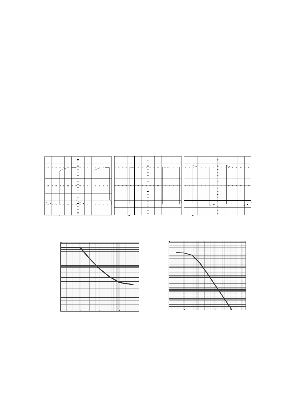
channel on. Press Auto Setup and adjust the time base and volts/div settings until the signal
on the screen contains two cycles (see figures below). Use the Trimmer tool (6) to adjust the
probe response to match the correct trim shown below.
[Note] Do not apply excess pressure to the screwdriver when you use it. The tip of
screwdriver are is easy to brake, because of made by plastics.
Undershoot
Correct
Overshoot
Typical Voltage Derating Curve
Typical Input Impedance
1.0E +02
1.0E +03
1.0E +04
1.0E +05
1.0E +06
1.0E +07
1.0E +08
1.0E +00
1.0E +02
1.0E +04
1.0E +06
1.0E +08
1.0E +10
Frequency[H z]
Zin[ohms
]
1
10
100
1000
0.1
1
10
100
1000
Frequency[M H z]
Voltage
[V
(DC+AC peak
)
]