D: auxiliary equipment – Allstar Products Group J6500 User Manual
Page 14
14
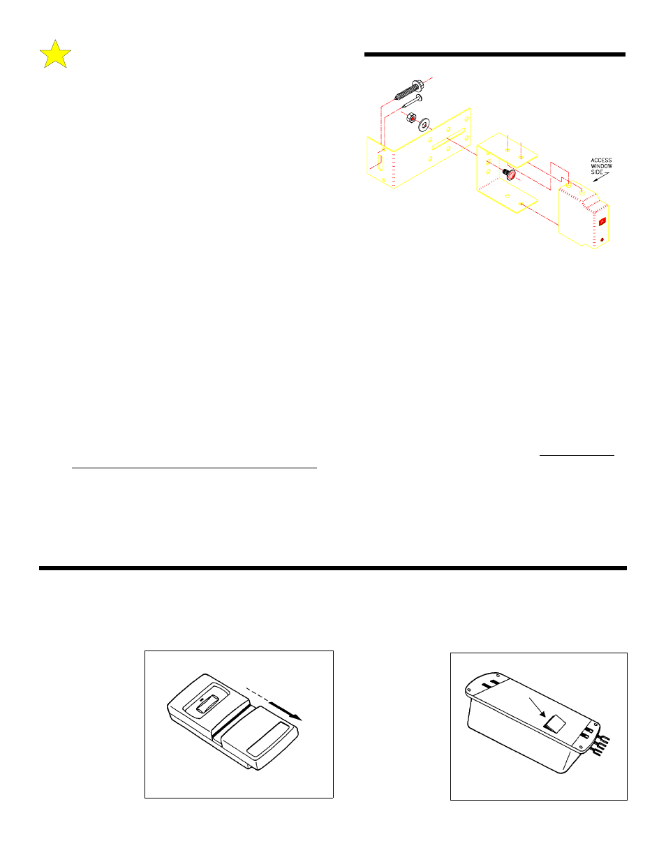
A. Attach the"U" brackets to the "L" brackets with a 1/4-20 carriage
bolt, washer and hex nut (provided). Insert the bolt from the
inside of the "U" bracket and hand tighten only at this time.
B. Place the transmitter and receiver units into their respective "U"
brackets. See Illustration, at right.
C. Connect the interconnect wire pair to the garage door opener
terminals marked "4" & "5". Although not required, it is
suggested that the "trace" be connected to Terminal 5. See
Wiring Diagram, Page 21.
STEP 5 :
Final Alignment and Test
A. Reconnect the power to the Garage Door Opener. Keep a
portable transmitter with you to control the garage door opener.
B. Place a solid object one foot in front of the transmitter or receiver. The red LED should go OFF and remain OFF until the
object is removed. NOTE: There may be a slight delay in returning to normal depending upon how long the photosystem
was blocked.
C. Move to the center of the door. Make sure the red LED light is on. Move a solid object slowly through the beam.
The LED should go OFF and then ON. If not, check the wire connections (see Step 3).
D. At this time set or recheck the down limit adjustment and reversing system adjustment of the garage door opener following
the procedure outlined in Steps 1 & 4, Pages 17 & 18. It is VERY IMPORTANT that the door opener's inherent features
operate as intended before completing the photosystem tests.
E. Place an opener insert box or a similar object (at least six inches high) on the floor at the center of the door. Now, attempt to
close the door. The door should NOT close from the portable transmitter, but will close with constant pressure from the
mechanical push button.
F. Remove the obstruction from the photosystem beam’s path. Close the door. Toward the bottom of the doors downward
movement, CAREFULLY move a solid object across the path of the beam at the center of the door. The door should
STOP, pause for approximately one second and OPEN. Retest, breaking the beam one foot in front of both the transmitter
and receiver unit while the door is moving downward. The door must STOP and OPEN each time. If not, re-align the
photosystem until proper operation is obtained.
G. Tighten all mounting screws and bolts.
104383
D: AUXILIARY EQUIPMENT
INSTALLATION OF RADIO CONTROLS:
The following instructions detail installation of Model 9931 Radio Controls. For other Radio models, see instructions
packaged with product.
104385
TRANSMITTER:
To gain access to
the Transmitter
Coding Switches,
remove the Battery
Cover from the
f r o n t o f t h e
Transmitter by
sliding it toward the
bottom of the
Transmitter as
illustrated.
104384
RECEIVER: The
Receiver Coding
Switches can be
accessed by
removing the small
door from the back
of the
Receiver using a
small screwdriver or
knife.