Vtr control cable pinouts, Standard vtr control cable pinouts – Autodesk Z800 User Manual
Page 49
VTR Control Cable Pinouts
Topics in this chapter:
■
Standard VTR Control Cable Pinouts
on page 45
■
VTR Emulation RS-422 Control Cables
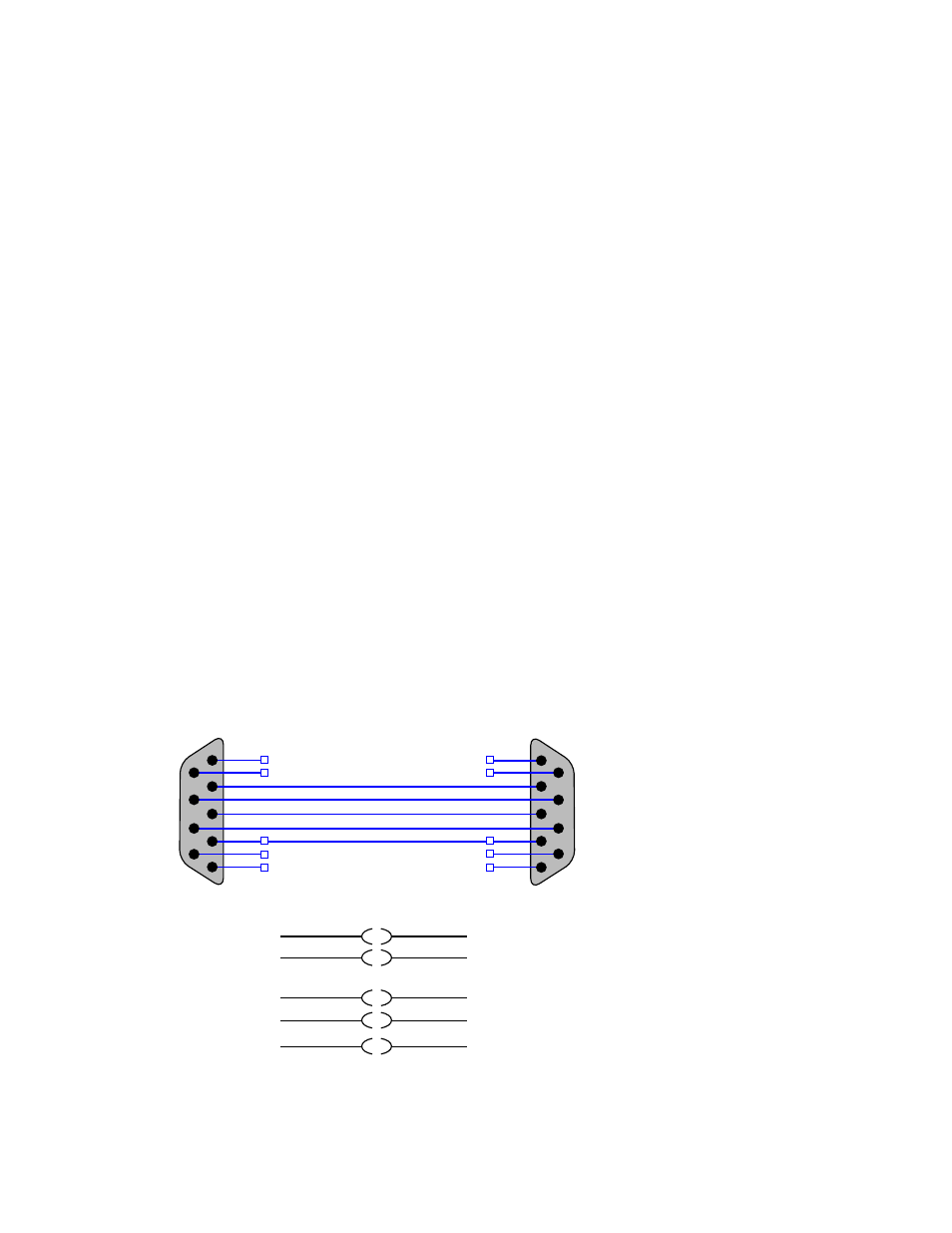
Standard VTR Control Cable Pinouts
The following diagram depicts the RS-422 control cable pinouts for the standard VTR control cable.
1
6
2
7
3
8
4
9
5
1
6
2
7
3
8
4
9
5
WHT
BLK
BLK
RED
GND
OEM-2K: MALE DB9
OEM-LH: FEMALE DB9
MALE DB9
2 - RX -
7 - RX +
3 - TX -
8 - TX +
2 - TX -
7 - TX +
3 - RX -
8 - RX +
4 - GND (SHIELD)
4 - GND (SHIELD)
PAIR 1
PAIR 2
Linux(AJA)
VTR
RS-422
A
45