Step (3) disconnect the battery leads, Electrical schematic – Superwinch C1000 (Motor Cover/Remote) - 453 kgs/12V User Manual
Page 8
LOCATION
Mount the winch to a firm base.
The structure the winch is attached
to must be capable of withstanding
a load greater than 1-1/2 times the
winch’s rated line pull.
The winch can be mounted in a
horizontal or vertical position. Do
not mount the winch where there
would be the possibility of it being
submerged in water. The winch is
weather resistant but not waterproof.
This winch MUST
be mounted
with the pull in the underwind direc-
tion. Improper mounting could dam-
age your winch, cause the brake to
not work and void your warranty.
Step (1)
Install structural support for winch.
See "Dimensions" section for winch
dimensions.
Step (2)
Mount the winch to the mount that
you have designed.
Mounting bolts supplied are the
correct length for use with a 1/4"
(6.3mm) thick mounting plate.
Do not substi-
tute any bolt
with strength weaker than
grade 5.
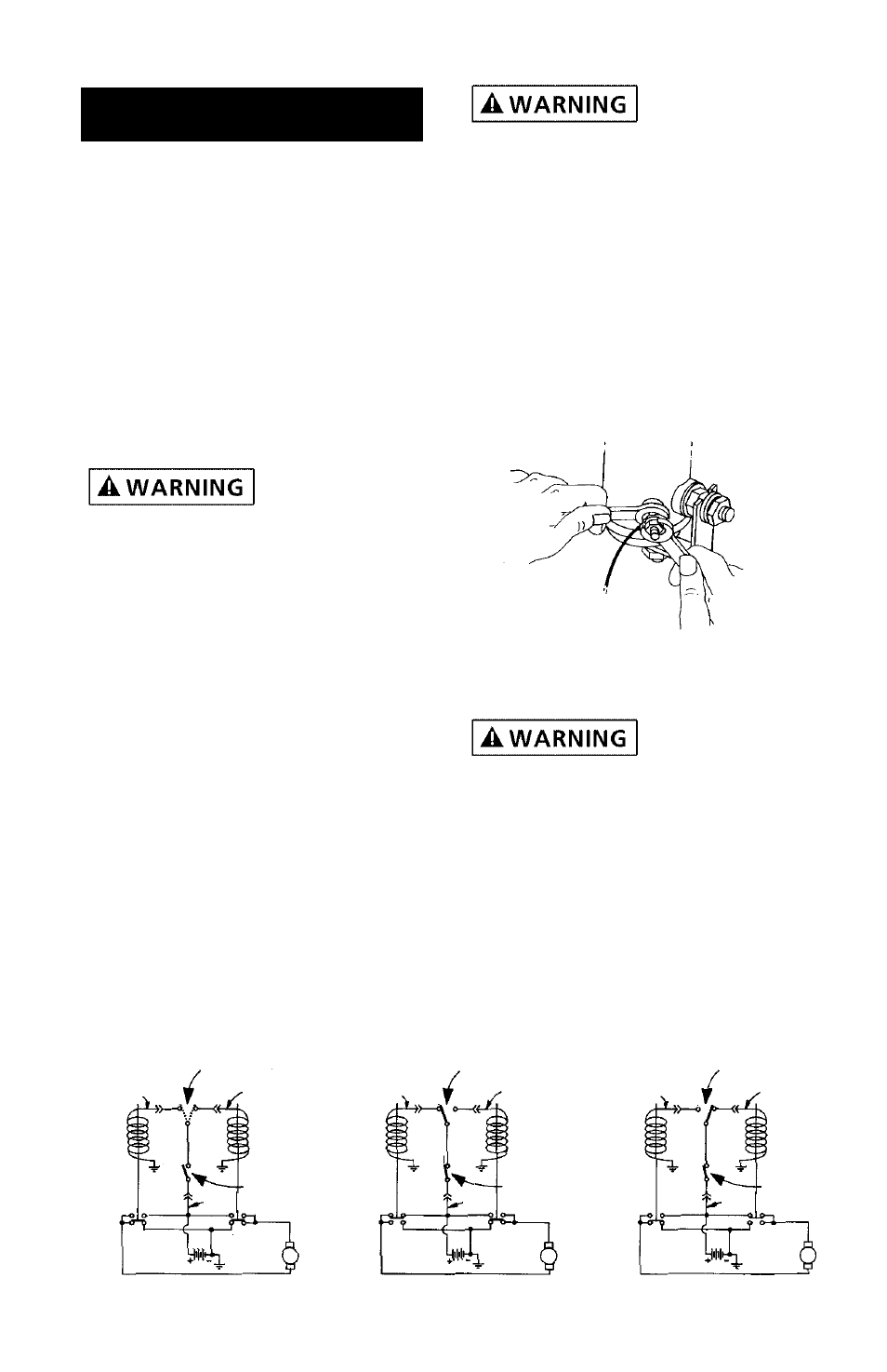
When attaching wire to the motor
terminals and solenoids (relays),
hold the inner nut when tightening
the outer nut. Do not allow the ter-
minals to rotate. It may cause inter-
nal wire breakage or part misalign-
ment. Be especially careful in pre-
venting the solenoid (relay) termi-
nals from rotating. Any rotation can
damage the solenoid (See Figure 1).
Step (3)
Disconnect the battery leads.
Batteries con-
tain gases
which are flammable and explosive.
Wear eye protection during installa-
tion and remove all metal jewelry.
Do not lean over battery while
making connections.
Step (4) Model 03003
Select a convenient location for
mounting the Solenoid Remote
Control Assembly. The solenoid
I N S T A L L A T I O N
Figure 1
7
REVERSAL SWITCH
(Switch may be in
Either Position)
OFF
REVERSAL SWITCH
(Rope-In position)
WIRE ROPE IN
WIRE ROPE OUT
REVERSAL SWITCH
(Rope-Out position)
Electrical Schematic
Green
Black
4
3
1
Trigger
Switch
Load
Line
White
NC
NC
Winch
Motor
Green
Black
4
3
1
Trigger
Switch
Load
Line
White
NC
NC
Winch
Motor
Green
Black
4
3
1
Trigger
Switch
Load
Line
White
NC
NC
Winch
Motor
7
Figure 2