32 figure 18. reversing hookup diagram, Customer supplied spst switch – LEESON Chassis Mount PWM Control: 175292.00 User Manual
Page 38
32
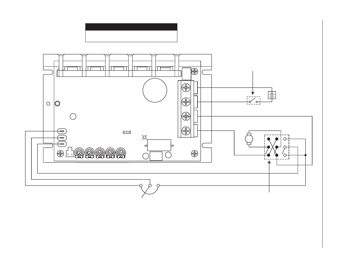
Figure 18. Reversing hookup diagram
Motor and battery wire must be a minimum
of 12 ga. and a maximum of 6 ga.
C A U T I O N
Customer Supplied
3PDT Center-Off
Center-Blocked Switch
A1
S1
S2
S3
-VDC INPUT
+VDC INPUT
TB501
MAX SPD
ACCEL
CUR LIMIT
IR COMP
MIN SPD
INHIBIT
POWER
1 2 3
JP501
C501
Q502
IL501
SO501
Q504
Q501
Q503
L501
C506
R502
2
C505
C504
A2
BATTERY
Customer Supplied
SPST Switch
POT LOW
POT HIGH
POT WIPER
MOTOR
+
-
This manual is related to the following products: