Voltage follower, Installation – LEESON Chassis Mount PWM Control: 175292.00 User Manual
Page 20
14
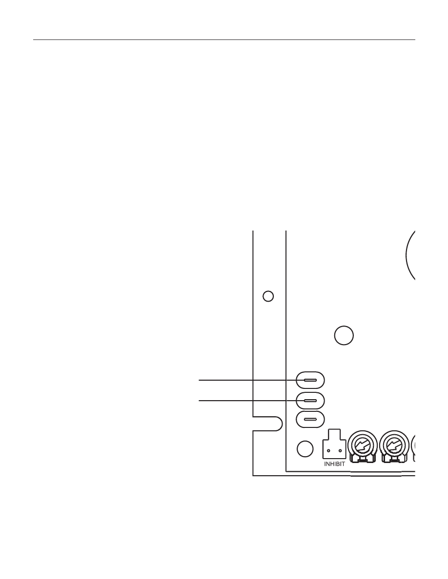
Voltage follower
Instead of using a speed adjust potentiometer, the drive may be
wired to follow an isolated (floating, or differential) 0–10 VDC signal
that is isolated from earth ground (Figure 8). Connect the signal
input (+) to S2. Connect the signal common (–) to S1. Make no
connection to S3. A potentiometer can be used to scale the analog
input voltage.
Figure 8. Voltage Follower Connections
0 - 10 VDC
SIGNAL INPUT (+)
SIGNAL COMMON (-)
SO501
C504
S3
S2
S1
MIN SPD
ACCEL
M
Installation
This manual is related to the following products: