Voltage follower – LEESON PWM DC Control: 174299 User Manual
Page 20
1
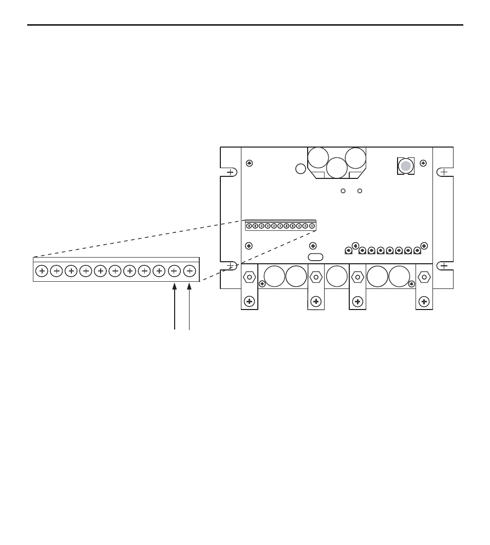
Instead of using a speed adjust potentiometer, the drive may be wired to follow a 0 - 5 VDC
signal (Figure 10). Connect the signal input (+) to S2. Connect the signal common (-) to S1. Make no
connection to S3. A potentiometer can be used as a voltage divider to scale the analog input voltage.
The analog signal common must be the same common as the battery common connected to BAT-. It
is acceptable to connect the negative side of the battery to Earth ground in some applications.
Voltage follower
TB501
S1
S2
+ _
0 - 5 VDC
Figure 10. Voltage Follower Connections
This manual is related to the following products: