Voltage follower, 9installation, Figure 6. voltage follower connections – LEESON Chassis Mount PWM Control: M1740009.00 User Manual
Page 15
9
Installation
L1
L2
A1
A2
S3
S2
0 - 5 VDC
ISOLATED VOLTAGE
SIGNAL INPUT
+
-
S1
H2
H1
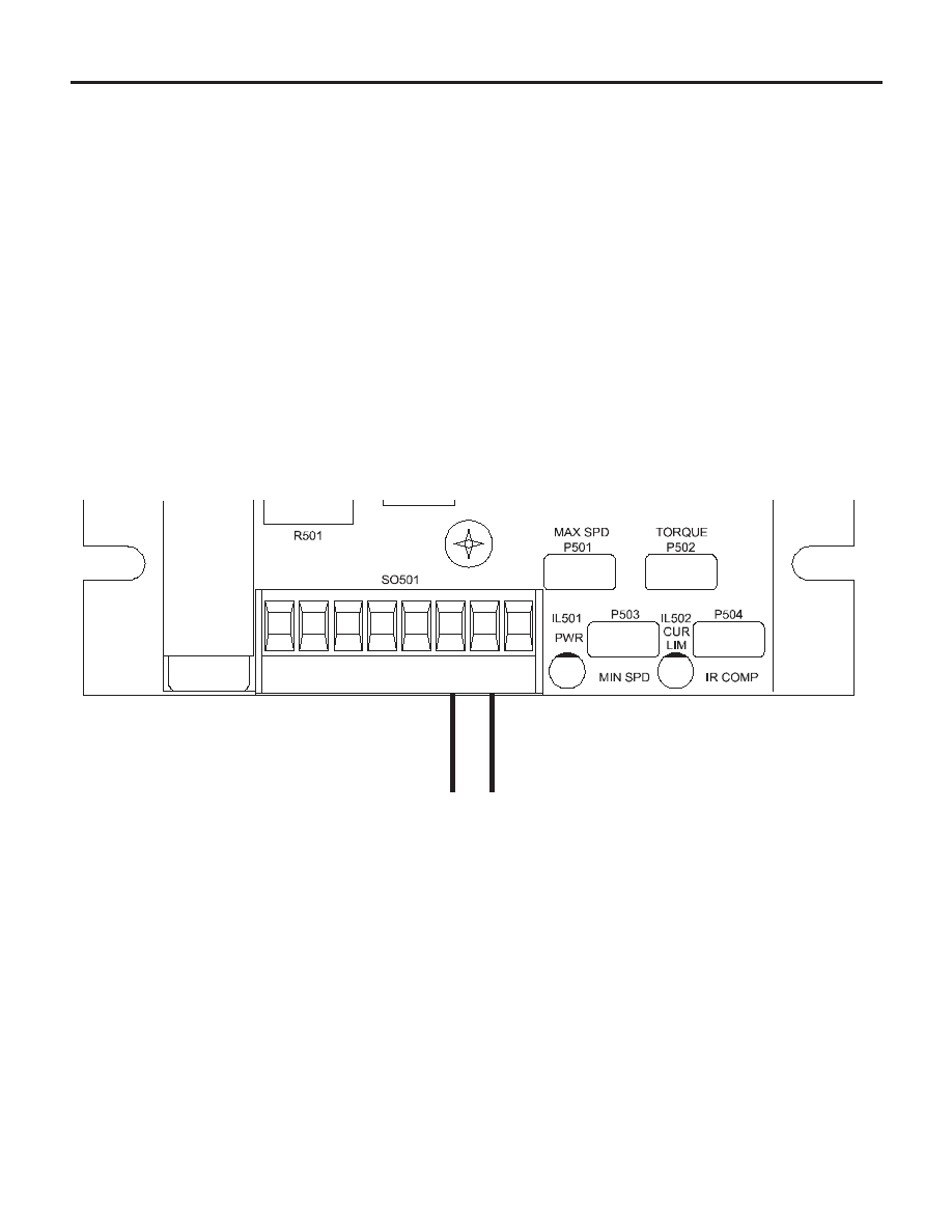
Figure 6. Voltage Follower Connections
Voltage follower
Instead of using a speed adjust potentiometer, the drive
may be wired to follow a 0 - 5 VDC voltage signal that is
isolated from earth ground (Figure 6). Connect the signal
input (+) to S2. Connect the signal common (-) to S1.
Make no connection to S3. A potentiometer can be used to
scale the analog input voltage.
This manual is related to the following products: