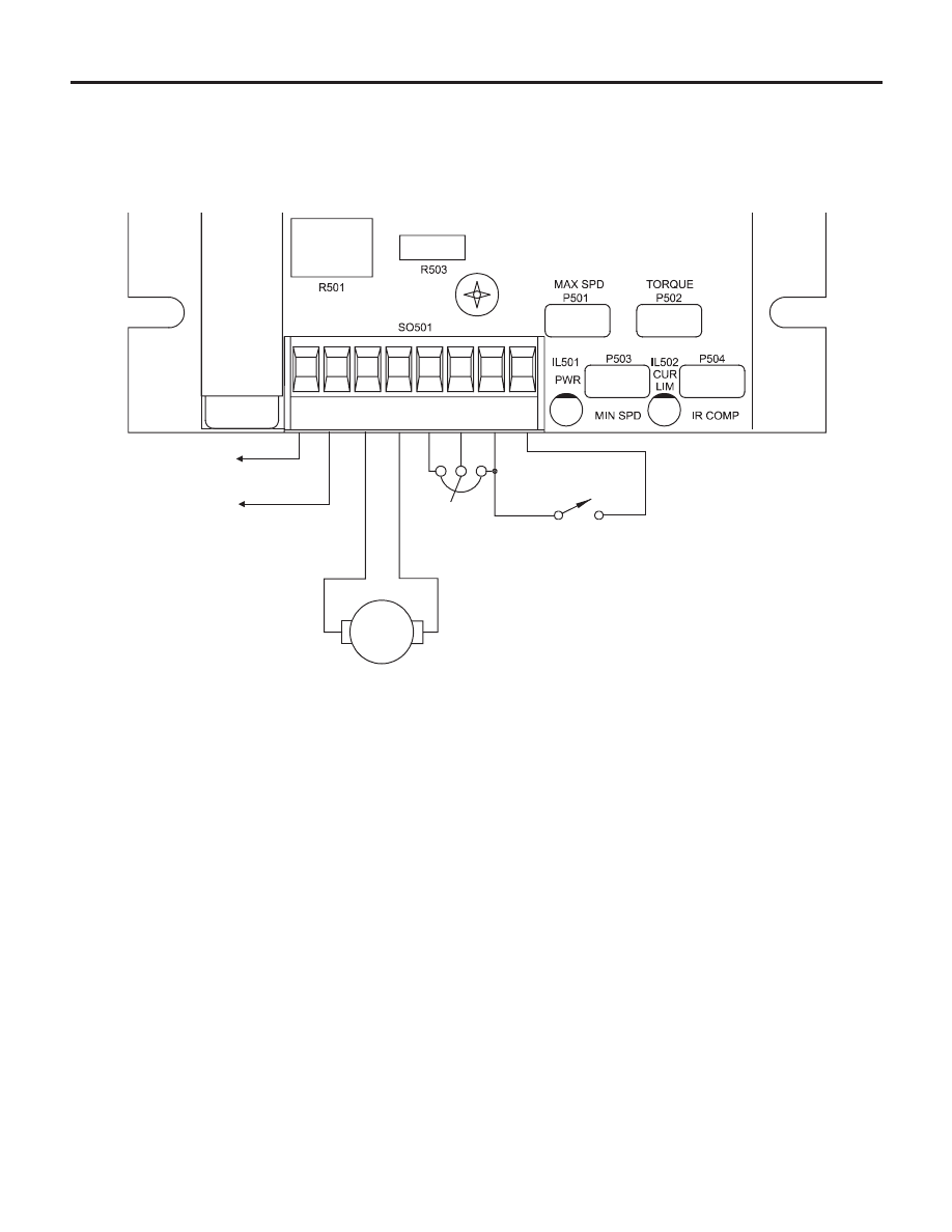
Connections, 8installation, Figure 5. drive connections – LEESON Chassis Mount PWM Control: M1740009.00 User Manual
Page 14
8
Installation
Connections
Assumptions: This drive series supplies motor voltage
from its A1 and A2 terminals. It is assumed throughout this
manual that when A1 is positive with respect to A2, the
motor will rotate clockwise (CW) while looking at the output
shaft protuding from the front of the motor. If this is
opposite of the desired rotation, simply reverse the wiring to
the motor from A1 and A2.
INHIBIT SWITCH
(optional)
10K
SPD ADJ
POT
CW
LINE VOLTAGE
115 VAC
MOTOR
L1
L2
A1
A2
S3
S2
S1
H2
H1
STOP
RUN
Figure 5. Drive Connections
This manual is related to the following products: