Heating cable installation – King Electric SRP self-reg, preassembled User Manual
Page 2
Pipe
Type*
5
‘
10’ 15’ 20’ 25’ 30’ 35’ 40’ 45’ 50’ 55’ 60’ 65’ 70’ 75’ 80’ 85’ 90’ 95’
100’
½”
M
A
B
C
D
E
E
E
E
E
E
F
F
F
F
F
G
G
G
G
G
P
A
B
C
D
E
E
E
E
E
F
F
F
F
F
G
G
G
G
G
G
1”
M
A
B
C
D
E
E
E
E
E
E
F
F
F
F
F
G
G
G
G
G
P
B
B
C
D
E
E
E
E
E
F
F
F
F
F
G
G
G
G
G
G
1 ½”
M
A
B
C
D
E
E
E
E
E
E
F
F
F
F
F
G
G
G
G
G
P
B
C
D
E
E
E
E
F
F
G
G
G
G
G
-
-
-
-
-
-
2”
M
A
B
C
D
E
E
E
E
E
F
F
F
F
F
F
G
G
G
G
G
P
B
C
E
E
E
F
F
G
G
G
G
-
-
-
-
-
-
-
-
-
2
½”
M
A
C
C
D
E
E
E
E
E
F
F
F
F
F
G
G
G
G
-
-
P
B
D
E
E
F
F
F
G
G
-
-
-
-
-
-
-
-
-
-
-
A
SRP12-6
B
C
D
E
F
G
SRP12-18
SRP12-24
SRP12-50
SRP12-75
SRP12-100
SRP12-12
Heating Cable Selection Table for Pipe Freeze Protection
* Type: M = Metal Pipe, P = Plastic Pipe
- Add 1 foot to the cable length for each valve or spigot.
- Chart is based on the lowest outside temperature of 0
º
F (-18
º
C) with a minimum of
½” thick insulation. Use 1” insulation for protection in temperatures down to -20
º
F (-29
º
C).
GENERAL NOTES
1. Verify that the heating cable is the correct length, wattage and
voltage prior to installation.
2. All welding, hydrostatic testing, and painting of the pipe
should be completed before the heating cable installation.
3. The piping system must be inspected to ensure that it is clean,
dry and has no sharp or jagged edges that could potentially
damage the heating cable.
4. Do not install the heat tracing before completion of the entire
piping system.
5. The cables must be installed a minimum of 10 inches away
from wood or any other combustible materials.
6. The minimum cable bending radius is 1/2 inch.
PREPARE FOR INSTALLATION
1.
Store the heating cable in a clean, dry place.
2.
Perform a pressure test on the pipe prior to cable installation.
3. Remove any sharp surfaces on the pipe that could potentially
damage the outer jacket of the heating cable.
4. Walk the pipe system and plan the routing of the heating cable
on the pipe.
ATTACH THE HEATING CABLE TO THE PIPE
1
. Verify pipe to be traced is completely dry.
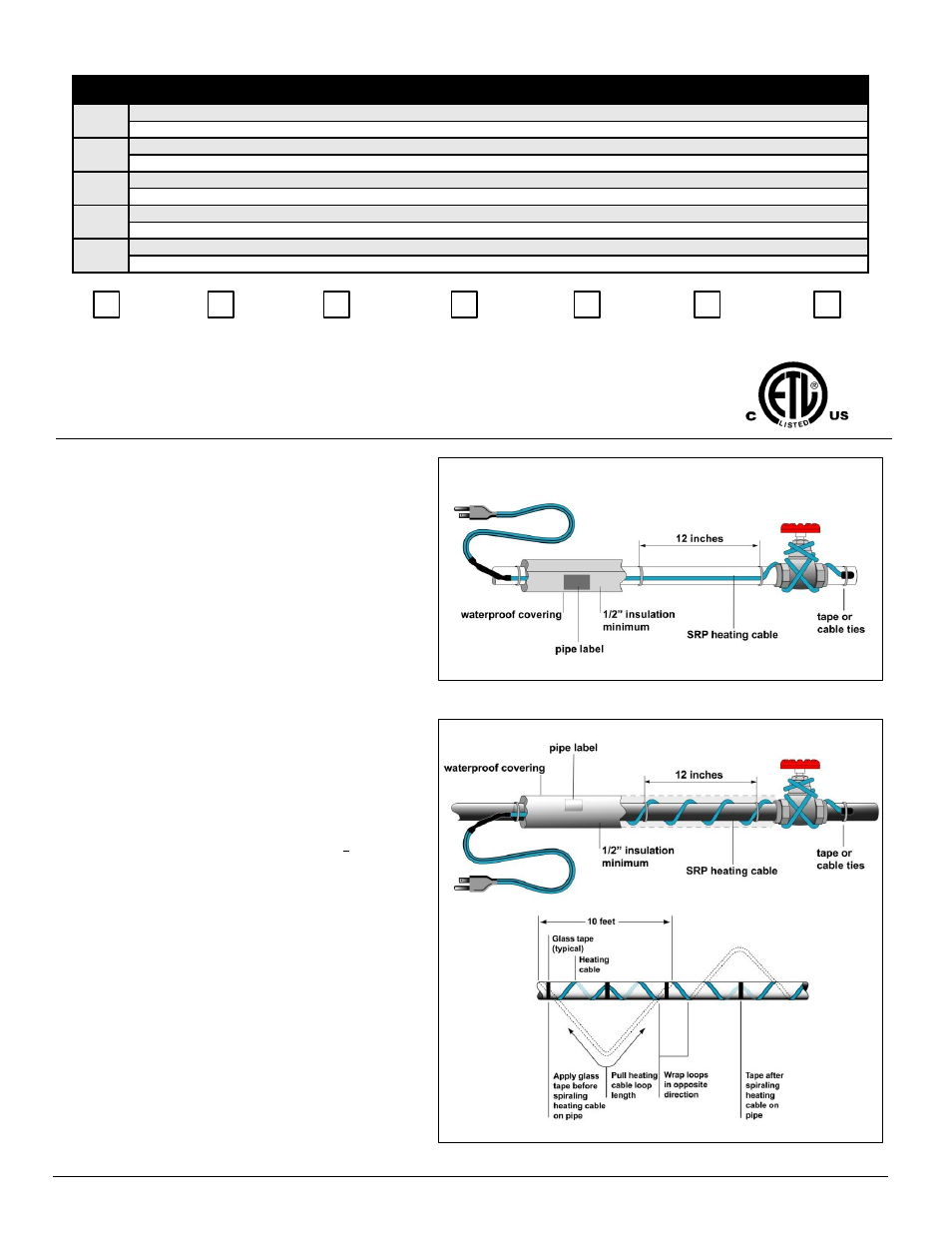
2. For straight tracing, install the heating cable on a the lower
half of the pipe; for example, in the 4 o
’clock
or 8 o
’clock
position as shown
in Figure
1.
3. For spiral tracing, install the cable as shown
in Figure 2.
4. Install the extra heating cable required for valves, flanges,
etc.
5. When applying spiral tracing, begin by suspending a loop of
cable every 10 feet as shown in Figure 2. To determine the
loop length, divide the length of pipe length and multiply by
10.
6.
For example, if you are using a 50 ft heating cable on a 40
foot pipe, leave a 12 foot loop of heating cable at every 10-foot
section of pipe. Grasp the loop in its center and wrap it around
the pipe. Even out the distance between spirals by sliding the
wraps along the pipe. Use glass tape (SRK03) to secure the
center of the loop to the pipe.
7. Fasten
the heating cable to the pipe at 1 foot intervals using
SRK03 fiberglass tape or nylon cable ties. Do not use vinyl
electrical tape, duct tape, metal bands or wire.
8. If there is excess cable at the end of the pipe, double
remaining cable back
along the pipe.
Heating Cable Installation
Figure 1: Straight Tracing
Figure 2: Spiral Tracing
Rev 8.19.12
www.king-electric.com
2