Ds−2b, Recommended switch settings by function, Fine adjustment for efficient operation – King Electric DS-2B User Manual
Page 4: Manual override switch operation, Typical load wiring
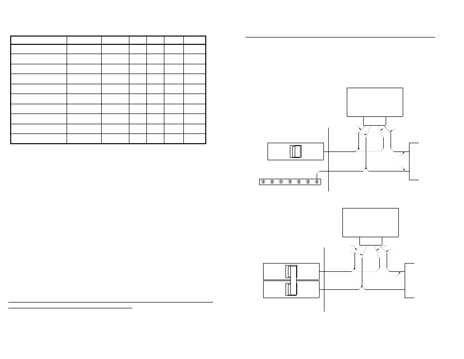
The relay inside the DS-2B acts as a switch. While not as convenient as directly supplying power for the
load this allows you to operate the DS-2B from one voltage while controlling a load of a different voltage
without adding an external relay or contactor. For example, the DS-2B can be powered from 120VAC but
can directly control a 24VAC signal for a boiler system or 240VAC for heating wire. The following diagrams
show some possible wiring schemes for connecting the DS-2B to your load. Your load may be a direct
connection to heat cable, a heater, a contactor coil, or a control voltage. For clarity the safety GROUND
leads are not shown.
Recommended Switch Settings by Function
Function
Trigger
Delay
LTC
DEL
RAIN
SNOW
Snow sensor w\o LTC
TT>AT
2 Min
OFF
OFF
OFF
ON
Snow sensor w\LTC
TT>AT>15
°F
2 Min
ON
OFF
OFF
ON
Snow controller w\o LTC
TT>AT
30-90 Min
OFF
ON
OFF
ON
Snow controller w\LTC
TT>AT>15
°F
30-90 Min
ON
ON
OFF
ON
Precipitation sensor
Not Used
2 Min
X
OFF
ON
ON
Precipitation controller
Not Used
30-90 Min
X
ON
ON
ON
Rain sensor
AT>TT
2 Min
X
OFF
ON
OFF
Rain controller
AT>TT
30-90 Min
X
ON
ON
OFF
LT thermostat w\o LTC
TT>AT
2 Min
OFF
X
OFF
OFF
LT thermostat w\LTC
TT>AT>15
°F
2 Min
ON
X
OFF
OFF
Fine Adjustment for Efficient Operation
The DS-2B is shipped with the TEMP and DEL adjustments in the center position, representing 39°F
(3.9°C) and 30 minutes of Delay-Off time respectively. Depending on local conditions the user may find
that fine adjustment of the controls may provide more satisfactory operation. If the sensor does not trigger
during very wet snows the trigger temperature may need to be adjusted higher. Conversely, if the user
notices false triggers during cold rains that do not freeze, the trigger temperature may need to be lowered.
The Delay-Off time can also be adjusted to provide clean melt-off without excessive running time. Fine
adjustment can both save operating expense and provide more reliable operation. However, to keep
reliability high, always make adjustments in small increments.
Always Use Care When Replacing The Front Cover
Be sure the front cover gasket is not pinched or rolled. Do not overtighten the front cover screws.
Manual Override Switch Operation
An override switch mounted on the side is provided for testing and special operational requirements.
Placing the switch in the “Automatic” position will allow the sensor to operate normally, activating the
controlled equipment as needed. Placing the switch in “Manual On” will close the load relay, activating the
controlled equipment. The “Standby/Reset” position prohibits triggering of the unit, clears any active delay
timer, and opens the load relay. In order to reduce excessive runtime for the heater the “Manual On”
mode will remain in effect for a maximum of 40 hours, then return to “Automatic” mode even if the
switch is still in the “Manual On” position. You may put the DS-2B back into “Manual On” mode by
switching to “Automatic”, then back to “Manual On”. This will restart the 40 hour timer.
If the override switch is placed in “Manual On” for less than 2 seconds, then switched back to
“Automatic” the controller will execute one delay off cycle. This can be used to clear a frost or hail
buildup without the danger of leaving the system in a continuous “Manual On” condition. “Standby/Reset”
can still be used to clear this delay off cycle.
4
Typical Load Wiring
The two load leads are N.O. contacts and do not supply power directly to your load
NEUTRAL BUS BAR
20A
LINE/L1
NEU/L2
YELLOW
YELLOW
LOAD
DS−2B
SWITCHED 120VAC
NEUTRAL
LOAD CENTER
20
A
LINE/L1
NEU/L2
YELLOW
YELLOW
LOAD
DS−2B
SWITCHED 240VAC
LOAD CENTER
120VAC In, 120VAC Load, Heat Cable or Similar (Strap DS-2B for 120VAC Power)
240VAC In, 240VAC Load, Heat Cable or Similar (Strap DS-2B for 240VAC Power)
5