Moisture sensor mounting & termination, Power & activation indicator, Preseason snow detection testing – King Electric DS-824 User Manual
Page 2: General safety instructions
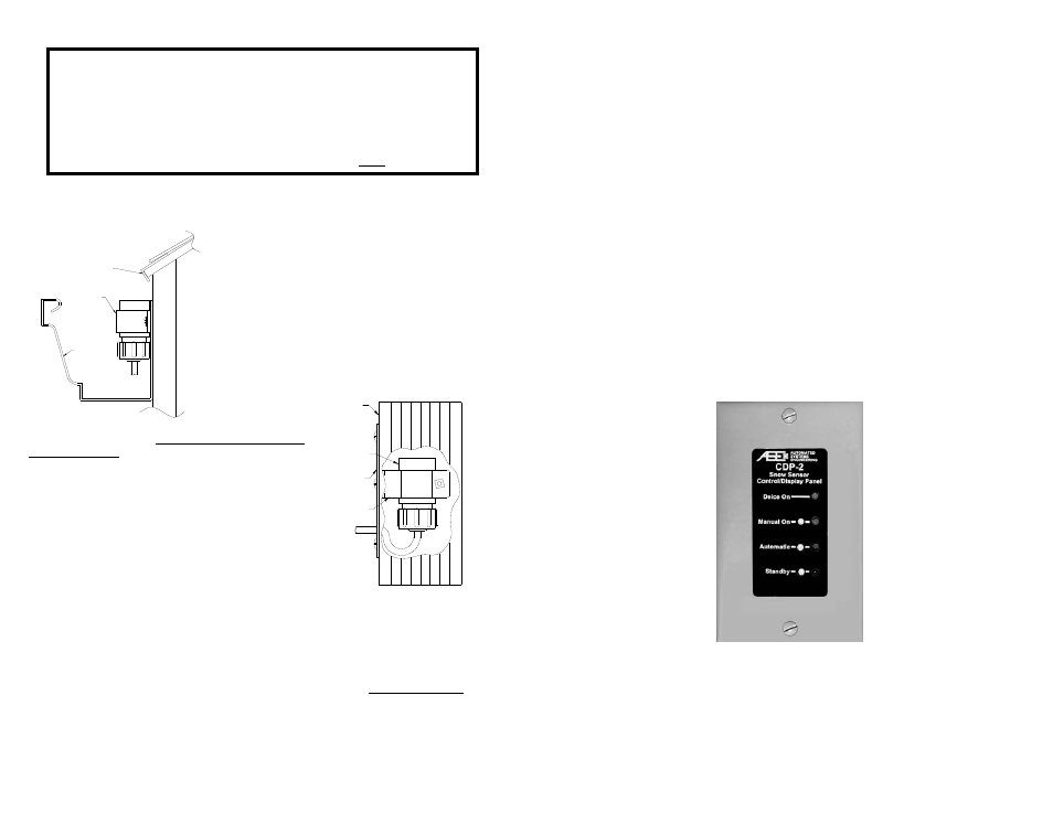
GUTTER
SENSOR
DRIP EDGE
Moisture Sensor Mounting & Termination
The remote DS-824 precipitation/moisture sensor may be
mounted in a number of ways depending on the application. The
unit operates at a safe 24 VAC/VDC and can withstand
immersion in water. For roof and gutter deicing applications the
sensor head may be mounted in the gutter against the fascia
board with a 1” “C”-style conduit clamp. Allow part of the sensor
grid to be exposed to snowfall. This allows the sensor to initially
trigger when snow starts falling and remain triggered as long as
the roof/gutter heater continues to drip melted snow from the
roof edge when temperatures are below freezing. The sensor
may also be installed inside and near the top of the downspout
using a 1” conduit hanger and mounting plate. As water is
melted in the gutter
it will run to the
downspout, hitting
and retriggering the sensor. We do not recommend laying the
sensor in the gutter. Constant immersion will corrode the grid
and the sensor may miss a windblown snow trigger.
The sensor cable comes preinstalled but may be shortened as
needed. Strip the outer insulation and shield from the cable and
terminate each conductor following the color code printed on
the circuit board. The bare drain wire should be installed into
the terminal marked “Shield”. Wrap a cable tie securely around
the cable in the enclosure to provide additional strain relief
between the flexible enclosure gland and the free end of the
cable. Please call for guidance if additional length is required.
Erratic operation may result if the proper cable is not used.
Selecting a Mounting Location for the DS-824 Enclosure
The rubber “boot” protruding from the bottom of the DS-824 enclosure is the temperature sensor. For proper
temperature detection the DS-824 must be mounted outdoors, away from furnace vents, dryer vents, and
other sources of heat. Note that, when powered, the DS-824 precipitation grid will always remain hot. This is
normal. This allows the grid to continuously melt snow and evaporate both rain and snow from the grid.
2
Power & Activation Indicator
A yellow lamp is mounted on the base of the DS-824 to indicate operational status. If this lamp is OFF the
DS-824 is not receiving power. If this lamp is steady ON the DS-824 is powered but not triggered. If this
lamp is FLASHING the DS-824 is both powered on and has activated the deicing system. Note that, even
though snow may have stopped, the DS-824 indicator may be flashing indicating the system is on. The
indicator will continue to flash during the Delay-Off drying cycle.
Preseason Snow Detection Testing
It is always a good idea to test the operation of the DS-824 prior to the winter season. Procure some clean
water and, if the outdoor temperature is above the trigger point, a can of spray component cooler (Radio
Shack Part #64-4321 or equivalent.) Clean the precipitation grid following the procedure outlined above and
allow it to dry. Apply power to the DS-824 and drip some of the water onto the precipitation grid, and then
spray the temperature sensor protruding from the base of the enclosure with the component cooler. Once
the temperature sensor has reached the trigger point with water still present on the grid the DS-824 will
activate. The user should hear the internal control relay close. Proper operation has been confirmed. Allow
the grid to dry completely. To clear the Delay-Off timer place the override switch into “Standby/Reset”, and
then back to the “Automatic” position.
Need Indoor Monitoring & Control?
Take a Look at the ASE CDP-2
Compatible with the DS-824
Simple Installation & Operation at a Competitive Price
Visit www.goase.com for more information
7
General Safety Instructions
1. THIS UNIT SHOULD BE INSTALLED, OPENED, AND REPAIRED BY QUALIFIED
PERSONNEL ONLY!
2. To avoid shock hazard do not open the front cover with power connected to the DS-824 or
any controlled equipment.
3. Limit input voltage to 22-28 VAC/VDC.
4. Replace fuse F1 with a 2 Amp 32 V or 250 V 3AG fast acting fuse ONLY.
DOWNSPOUT
SENSOR
MOUNTING
PLATE
1" CONDUIT
CLAMP