8 wiring instructions for motor and potentiometer – Joyce MA7007 User Manual
Page 6
6
1-8 Wiring Instructions for Motor and Potentiometer
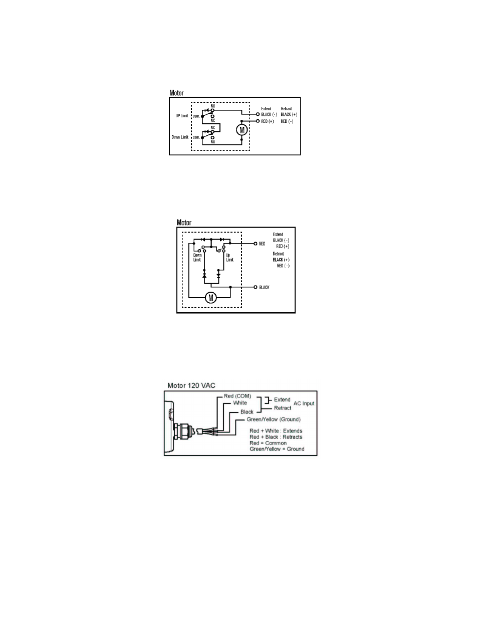
12 VDC Motor - MA0513
The actuator will extend when the red wire connects to the positive lead and the black wire
connects to the negative lead. It will retract when the black wire connects to the positive lead the
red wire connects to the negative lead. See Figure 3 below.
Figure 3 – Motor Schematic MA0513
12 VDC Motor - MA1527, MA2547, MA3507, MA3527, MA4514, MA7007
The actuator will extend when the red wire connects to the positive lead and the black wire
connects to the negative lead. It will retract when the black wire connects to the positive lead the
red wire connects to the negative lead. See Figure 4 below.
Figure 4 – 12 VDC Motor Schematic MA1527, MA2547, MA3507, MA3527, MA4514, MA7007
120 VAC Motor - MA1527, MA2547, MA3507, MA3527, MA4514, MA7007
The AC actuator will extend when the red wire connects to the white lead. It will retract when the
red wire connects to the black lead. See Figure 5 below.
Figure 5 – 120 VAC Motor Schematic