J. diagrams for vertical venting, Part 8, Gas piping – HTP MC120 User Manual
Page 48: A. gas connection, Part 8 – gas piping
48
LP-171 Rev. 4.10.14
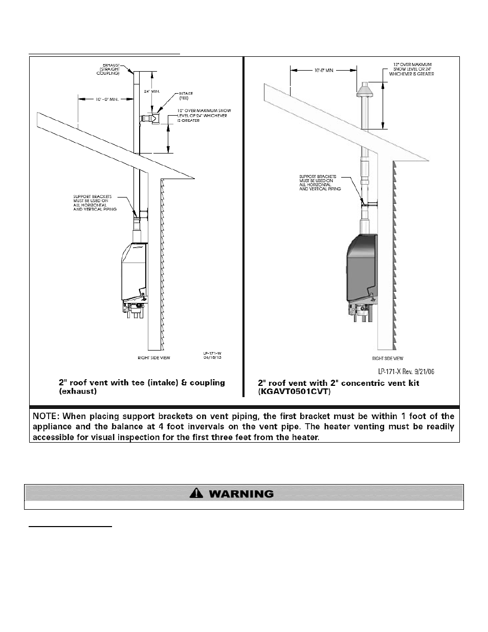
J. DIAGRAMS FOR VERTICAL VENTING
Figure 26
– Venting
PART 8 – GAS PIPING
Failure to follow all precautions in this section could result in fire, explosion, severe injury or death!
A. GAS CONNECTION
Connect the gas supply to the system following state and local plumbing codes. Use the supplied ball valve at the inlet to the system.
Make sure the gas supply line fits as shown in Figure 27.
The gas supply shall have a maximum inlet pressure of less than 14" water column (350 mm), ½ pound pressure (3.5 kPa), and a
minimum of 3.5" water column. The entire piping system, gas meter and regulator must be sized properly to prevent pressure drop
greater than 0.5" WC as stated in the National Fuel Gas Code. This information is listed on the rating plate.
NOTE:
Maximum inlet gas pressure must not exceed 14” w.c. (3.5 kPa).